DIY Electric Car Forums banner

Tesla 10Kw Open Source Charger Controller

3 reading
130K views 645 replies 35 participants last post by  Kevin Sharpe  
#1 ·
So I've had a first look at the Tesla Gen 2 10Kw charger. Now , making one of these work as is with CAN messages is near on impossible due to the level of integration of the charger and the car. So I decided to have a look inside. Seems it uses 3 x 3.5kw modules linked back to a central logic board. Each modules connects to the logic pcb with 8 wires.

So far i have identified GND , +12v , +5v and a 500k canbus. Two lines seems to carry analog signals and one seems to be open circuit. Attached see some CAN captures from this internal network. I may be wrong but I bet it will be easier to work out these messages and get the individual charger modules to wake up.

So plan is to design a little breakout board so I can monitor the signals on a live car during the charge process and log the CAN messages.

Stay tuned:)
 

Attachments

#2 · (Edited)
Good start, however mind explaining what you hooked up and what you powered on?

Looks like the chargers all put out data, the same data.

example first message per unit: 0x207, 0x209, 0x20B.

14 messages a piece, that is quite a bit. But probably not all will be required.

Would you mind hooking up 230V to a charger section to see some data change?
 
#5 ·
Looks interesting. I mostly use an arduino due with savvycan for logging. I do also want to monitor all the lines and have a plug and play solution as I don't want to go cutting and soldering on another persons working car:)
 
#9 · (Edited)
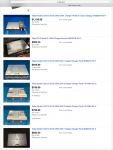
A search for "Tesla charger" on eBay finds 7 chargers for sale in the US today. Prices range from $550 to $1190 although you can find much cheaper examples via salvage.

What I really like about this open source development is the potential for a low cost ~22kW 3 Phase AC charger by using two in parallel... we have lots 22kW charging all across Europe :cool:

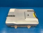
Note that Damien is working on the "Gen 2" charger which can be easily identified by the lack of a Tesla identifier stamped on the metalwork. This version is the one to buy IMO. Here's why;

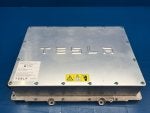
The "Gen 1" charger has a reputation for being less reliable than the "Gen 2" when fitted into the Model S. It's easy to identify with the word "TESLA" stamped on the metalwork. Jehu has a great video looking at whats inside here.

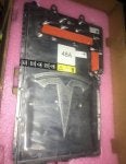
The "Gen 3" charger is lower power than the previous generations being restricted to 48A or 72A AC depending on the hardware version. It also appears to have the control board buried under the adhesive covered power boards. It's easy to identify with the Tesla "T" Logo stamped on the metalwork. Three great teardown videos are available here and a fourth which will remove the power PCB's (and hopefully reveal the controller) has been promised :)
 

Attachments

#14 ·
Progress. Managed to isolate charger block one and get it to stay enabled separate from the Tesla logic board. It spits out 13 CAN IDs. Took a log. Its on the github : https://github.com/damienmaguire/Tesla-Charger

Question is : What now .....
 

Attachments

#17 ·
I've grabbed a few more logs of the internal CAN network and uploaded to github. Few things falling out of this :


  • The CAN busses are tied together and the control board broadcasts 5 IDs to all the charger modules
  • The charger modules pump out 15 CAN IDs each. Each ID is incremented by 2 and depends on a set of jumpers on each 12way interface plug on the module.
I suspect all these charger modules are programmed the same. The nasty stuff stopping us just running the charger is on the logic board. If I can get a capture from a car before , starting and during a charge event and play this back to the modules I think they will wake up. Of course I could be way wrong about this. I guess I'll know if a Falcon 9 first stage lands on my house.
 
#19 ·
Tom , this is an internal CAN network in the charger between the logic board and the charger power modules. It would not be available externally to the charger. It's a GEN 2 charger but not sure what years that would be ...
 
#22 ·
The chargers seem to be found on the powertrain CAN bus (BUS3). The same one that the inverters are on. The FC CAN seems to actually be single wire CAN from the super charger port. It runs to the BMS and charger and while I can't find it right now I believe it goes to the charge port too. Their schematics can be tough to follow - one device will have its pinout spread across 12 pages.
 
#26 ·
I took a look at your logs. Its hard to see much in there yet as really nothing is hooked up and so you have very limited information to find. The obvious immediately interesting things would be the pack voltage/current and the AC mains voltage/current. I would imagine that all of the boards report these things.

It seems like even absent a log from a car you might be able to provide AC voltage to a module and perhaps even vary that voltage a bit to see if we can find the difference in the CAN traffic. Likewise, at a different time you might be able to provide voltage on the output of the charger in order to find where it reports the battery voltage that the module is seeing. This can likewise be varied to help find the difference. I'd think it would be pretty safe to do both tests with fusing. It'd sure help to narrow down some of the traffic you're seeing. I'm not sure why each module needs 15 messages. They must transmit an awful lot of information in there! Probably there would be temperatures as well. Do you happen to have a hair dryer for your luxurious locks? Perhaps you could heat one of the modules up and see what that does to the CAN messages.
 
#27 ·
Rigged up the Variac and did a few logs on one module. Swept the mains input up and down , flicked it directly on and off 0,230vac. Rectified the variac and swept the dc input from 0 to 350vdc and then flicked it on and off 3 times on another log.

Used a 230v 100w filament lamp to limit current.

Logs on the github : https://github.com/damienmaguire/Tesla-Charger
 

Attachments

#29 ·
So I think this will come down to the CAN messages. As it will be a few weeks before I get the capture from a car I'm going to jump the gun a little and work up a replacement open source logic board.

Basics I have in mind so far :


  • Due SAM3 processor with two CAN transceivers. One talks to the power modules the other talks externally.
  • USB port on board to program desired settings and upload firmware.
  • replicate as many of the Tesla external connections as possible e.g. control pilot , proximity etc
If anyone has any ideas or needs now is the time ....
 
#30 ·
If anyone has any ideas or needs now is the time ....
Great work as always :D

Can you add support for multiple chargers like the Tesla master/slave architecture? Supporting up to four (~40kW) for high end car/truck applications and sixteen for home-brew Superchargers (yes I'm serious :eek:) would be amazing.

Can you also consider how we support switching between one and three phase inputs? I guess we need a mechanism for the 'master' charger to switch contractors on the AC input?

Please include the ability to update the firmware externally... I don't fancy removing the charger each time :)

And finally, can we have programable I/O on any spare pins so we can cope with all the things we've forgotten? iirc Collin/Jack at EVTV developed some innovative hardware that can be configured to support lots different I/O requirements and I believe that's available open source.
 
#32 ·
So ganging the chargers up whether it be in a vehicle or Diy supercharger can be handled in software over the external CAN bus. We have lots of spare pins in the external connector so bringing out the USB or serial for software upgrades should be no problem. Likewise I'll come up with something for I/O expandability.

That said I'm not going to try and get it right first time here. I'll get a V1 board done fairly quickly so we can prove it works once I get a CAN capture from a car. It's a small pcb so minimum cost.

Connector hunting was fairly easy on this one. The internal connector for the power modules is a 24 way JST. Same as on the large drive unit logic board and the external connector is a 30 way Samtec IPS1-115-01-S-D.

Of course none of this will work if the CAN traffic is weird in some way or contains encryption etc etc. My sense of it is though they will keep the internal network simple but who knows.

Then it's on to the gen 3 charger ..... :D
 
#33 ·
So here is a look at where I am going with the logic board. Obviously not finished yet just a snapshot of current progress. I'm aiming to be pin compatible with the oem X042 connector so the Tesla inlet will connect right up and the charger will look after control pilot , latching etc.
 

Attachments

#39 · (Edited)
That makes no sense to me.

Can you please provide an example?

0x207

0x14 0xAA

that would mean

00010100 10101010

010101010

170

However:

0x13 0xA8

0001 0011 1010 1000

424

Plus an unsigned 9 bit int would with a 1 in the lift most bit would result in a value above 256 which is not possible for AC input voltage.

However

Damien what do you have for AC voltage in ireland? because if you just look at byte 1 (D2) it might just be a 8bit int which maxes out at 231