DIY Electric Car Forums banner

Tesla 10Kw Open Source Charger Controller

1 reading
130K views 645 replies 35 participants last post by  Kevin Sharpe  
#1 ·
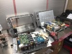
So I've had a first look at the Tesla Gen 2 10Kw charger. Now , making one of these work as is with CAN messages is near on impossible due to the level of integration of the charger and the car. So I decided to have a look inside. Seems it uses 3 x 3.5kw modules linked back to a central logic board. Each modules connects to the logic pcb with 8 wires.

So far i have identified GND , +12v , +5v and a 500k canbus. Two lines seems to carry analog signals and one seems to be open circuit. Attached see some CAN captures from this internal network. I may be wrong but I bet it will be easier to work out these messages and get the individual charger modules to wake up.

So plan is to design a little breakout board so I can monitor the signals on a live car during the charge process and log the CAN messages.

Stay tuned:)
 

Attachments

#535 · (Edited)
Also, only apply AC power post commanding on with 's' for the most reliable result.

The case of the charger says 50V minimum output, so it should be fine. So try raising the ac current limit to 2A and then retrying with the right sequence.

You planning on running two chargers in master slave configuration without an evse?

If so please have an external breaker and rcd as you are getting into a level of power where it is no longer a joke. Plus a nice big red 'oh shit' button to cut voltage to the enable lines for a safe shutdown.
 
#537 ·
Tom,


The test with the EVSE says:


‘x1’ – set it to can mode Master
‘a1’ – set it to autostart mode
‘c5’ – 5 amp ac input limit per phase
‘vxxx’ – xxx replace with end voltage limit
‘t2’ – set to type 2 socket or set it to ‘t1’ for the type 1 socket ‘p3’ – if all modules are on their own phase, else use ‘p1’

To initiate charge connect HV to charger and insert EVSE plug into socket.


If all works as expected change the input limit to match the wiring and breaker limits.


But when using an EVSE with the ControlPilot the EVSE is taking care of the max input limit /current isnt it ?
 
#539 ·
This limit is the last one that is applied when calculating max AC draw.


Ok, just to be clear:
For example the EVSE CP says max AC is 5A, the charger setup says 10A, the charger is limiting itself to 5A ?
Or when the EVSE says max is 10A, the charger setup is 5A, it is also limited itself to 5A ?


So the least amount of AC current defined either from the CP or the charger setup is the one thats is active ? The least restrictive is the most effective ?
 
#540 ·
the steps are as follow:

when using an evse

current request:
1. EVSE max current
2. 1 phase or 3 phase, one phase is divide by 3 and 3 phase is do nothing
3. if the current request is now larger than the AC limit (amount of phases respecting) limit it to AC current max setting.

This way the lowest value always wins. And this way everyone remains happy, expect if you set your AC current limit wrong in your car/vehicle.
 
#541 ·
Trying today to get the charger working with an EVSE J1772 USA single phase 240 configuration...

- Somehow '255' got stored for the parameters.type on the EEPROM. Needed to increment the EEPROM_VERSION in Config.H to force it to (on the next run) load a '1' for Type1 (i.e. J1772). After this it correctly detected the Proximity signal.

- I couldn't get 'auto charging' to work. Once HV DC applied, and EVSE plugged in, I still needed to input 's' on the Serial Monitor to make it start charging.

- Some odd behavior once it started...
1) All the modules activated, but flickered a number of times, relays clicking
2) DC request for 1000V listed in the log!

- I tried with 3A request to start with and on a second run increased this to 6A, but got the same behavior.

Attached is the log (edited for brevity) showing the startup and some activity I believe occurred as the modules activated/deactivated (LEDs on/off).

Any help interpreting this would be much appreciated.

Thanks
Jeff
 

Attachments

#542 ·
Code:
Module Cur Request: 1000 DC total Cur:0.09 DC Setpoint:380
the 1000 is the 1amp request from the module.

also your 380V charge request is quite low if the battery is already at 367V, this does cause issues i believe.

It does not look like the software here is at fault.

How did you have it working before?
Please write all the variables after you update the software.
 
#545 ·
Today I got to run the Gen 2 charger from 3 phase power for the first time courtesy of a nice old 100kva smokey diesel generator:D


One of the things I worried about was the neutral current when running the 3 modules at full power as it would be almost 50A AC on the neutral and 16A per phase. However, when running on 3 phase, the modules shift their PFCs by 120 degrees resulting in almost zero neutral current.:)
 
#547 ·
I can now confirm, the slave mode, can master and standalone work.

Latest code: https://github.com/tomdebree/Tesla-Charger

just a quick explanation on the Can Modes, set by 'x' followed by number:
0-Standalone, to be used when no slaves are connected (version with elcon control to follow)
1-Master, to be used when a slave charger is connected on can
2- Master Elcon, to be used when a slave charger is connected on can and control commands are sent via can by other controller
3- Slave, to be used with other charger configured as Master or Elcon master
 
#549 ·
This is excellent new.

I have both a master and a slave Gen2 charger waiting for surgery.

Its going to be awesome.
Three phase when ever I can get to it......
All the chargepoint in our city has three phase 32A Type 2 tethered EVSE.
I will be able to use the 22kw power from them :D:D:D


Cant wait to setup the testbench.

Big thanks to Damien and Tom for this great work..

/Per
 
#552 ·
Slave chargers make no difference.

I got one working without changing a thing in code.

Updated github code below

https://github.com/damienmaguire/Tesla-Charger

Changes:

- Introduction of simple DC current limit, calculation:

DC voltage/AC voltage* DC current limit = AC current limit

if you want this to not be used just set the DC current limit to 45 amps.
 
#553 ·
More updates on the software.

I have had the request to allow changing of the external canbus speed.

Now using command '1 250' you get a speed of 250k baud and using '1 500' you get a speed of 500k baud ect.

Github
https://github.com/tomdebree/Tesla-Charger

Anyone currently running the opensource board please feedback any issues or requests.
 
#554 ·
Update 09/08

Added feature:
'd' for display stored parameters in eeprom - this will give you a dump that you can save for later reference, or loading into a 'fresh' charger.

plus will help me/us out when you have issues.

note: currently untested as I am on vacation.

Github:
https://github.com/tomdebree/Tesla-Charger

I wonder how many chargers are currently on active duty with the opensource board and code. I know of +/- 10 so far,most of which are in the UK.
 
#556 ·
Update 09/08
I wonder how many chargers are currently on active duty with the opensource board and code. I know of +/- 10 so far,most of which are in the UK.
We will be running dual chargers active duty here in about a week.
I am wondering though about the outputs on the charger. Are they switch to ground with an internal pull-up or are they switch to 12v with an internal pull down? thanks!
 
#555 ·
Hi all,


I posted a month back or so about trying to get the open source board and charger system working, and I was having some issues getting the charger to enable. The good news is I did get it working and charging at 10kW, though we haven't put it into "active use" quite yet. Thanks everyone here for all their hard work, It's a really clean solution to getting a homebrew charging system working!


I've been trying to get a second unit (also master) working independently, and have been having some weird troubles there. I've taken a board that's working with my first charger, plugged it into my second charger, and it's failed to operate. I don't have a log on hand, but it seems the measurements of DC voltage and AC current are way off. My 360V battery is being reported as 504-506V on each module, and all three modules report a constant AC current in of 29.86A even when no current is present. When I plugged in a 36V battery into the DC output, the modules reported the voltage to be 44V and an AC current of 29.86A even though my AC supply wasn't plugged in. The sequence of audible clicks is correct, and the LEDs on each module operate in the same fashion as the first (working) charger.


Has anyone encountered faulty readings like this? It's a salvaged Gen2 master charger, the same as my first unit, so I suppose it's possible that the second unit is damaged, although it looks to be in perfect physical condition. I expected to be able to swap boards between the two units and have them operate identically.


-Ryan
 
#557 ·
... but it seems the measurements of DC voltage and AC current are way off. My 360V battery is being reported as 504-506V on each module, and all three modules report a constant AC current in of 29.86A even when no current is present. When I plugged in a 36V battery into the DC output, the modules reported the voltage to be 44V and an AC current of 29.86A even though my AC supply wasn't plugged in. The sequence of audible clicks is correct, and the LEDs on each module operate in the same fashion as the first (working) charger.

Has anyone encountered faulty readings like this? It's a salvaged Gen2 master charger, the same as my first unit, so I suppose it's possible that the second unit is damaged, although it looks to be in perfect physical condition. I expected to be able to swap boards between the two units and have them operate identically.
-Ryan
Hi Ryan,

I have noticed that between the three modules on my first charger - two would agree on the battery voltage and one would be 2-5V lower. Nothing like the voltage difference you are seeing. The consistent readings were 1-2V away from my voltmeter reading. My second charger exhibits similar variances.

Jeff
 
#558 ·
I've having on-going charger problems, fitted with Damien's Gen2V3 board. I've now tested on a different charger and am seeing the same symptoms/data reported as with my first charger (nothing like testing with spare $1000 parts!).

So it pretty much boils down to...
1. Charger (Controller) is not externally wired up correctly
2. Charger module firmware (for the version of chargers I have) is slightly incompatible with Damien & Tom's software
3. I've configured Tom's software incorrectly
4. Controller board is not working correctly
5. Power source to the Charger/Controller is not sufficient (amps/continuity)

Symptoms
Software reports that AC voltage and DC battery voltage correctly. Software also reports HI on the Enable (IN1) line. All the LEDs come on, relays click, FLT flag set almost immediately, AC Current climbs for 1-2 seconds and then drops to a minimal level (doesn't report 0 on all three modules - but so close to zero to be zero). All three modules reset (LEDs flicker off/on) about every 5 seconds.

1. External Connections
- 12v and ground provided to the charger
- internal CAN lines connected to an EVTV CANDUE
- IN1 connected to 12v
- LATCH not connected
- external CAN not connected
- OUT1 not connected

2. My chargers are 00-K and 00-J versions.

3. V400, C7, Type 1, 120V, singlephase. Also tested with a US EVSE (240v, singlephase, 40A)

4. I swapped the Controller board from charger 1 to charger 2 for the test - changing nothing else

5. I've got the 12v/GND to the module connected to a power supply box I built out of an old computer PSU.

Potential things to chase
- How to ensure the charger isn't seeing a loss of isolation?
- 12v power supply isn't dropping and causing the modules to reset?
- What software configs have other US users had success with?
- How to 'debug' the controller board (is it glitching the module enable lines?)

Jeff
 
#561 ·
I'm welcoming any ideas people might have on the Tesla Gen2 charger and how to get it working fully. Especially interested in anyone in the US who has gotten the charger working on single phase AC power.

Update on the status of my charger testing...
- Discovered that I can charge with any 1 or any 2 of the 3 modules, but I just can't get all 3 modules to charge at the same time
- Same charging behavior across two separate chargers
- Supplied the charger with two different 12v power sources (PSU and via the Tesla DCDC converter) but no difference in charging behavior
- Charger takes 12v 0.6amps with 1 module, 1.3amps with 2 modules, but for 3 modules it drops back to 0.6amps (but never enters a charging mode).
- No difference charging with 120v or 240v (singlephase)
- No difference charging at 1A/module, 2A, 3A, 3.5A...

Setup...
- US spec chargers 1014963-00-K and 1014963-00-J
- 120v AC input, Singlephase
- DC charging 400v target, battery currently at 369v
- Gen2 v3 charger controller from Damien (EVBMW)
- Latest software from Tom de Bree

What this rules out...
- Malfunctioning charger (two chargers produce exactly the same result)
- 12v power source to the charger
 
#564 ·
Further to Ryan's post (Cyco90), we purchased a 3rd charger and successfully got that running. It looks like there was a problem with one of the other chargers. Both working chargers exhibit identical behaviour. Using a 240V single phase input at 42 amps, we get 26 amps DC output to our 350V pack (9.2kW). Next step is to see if we can parallel the chargers for 18.4kW out. This should charge our modified Bolt Pack in just over 2 hours!

The only issue seems to be that both chargers read the AC current incorrectly. They show the 42 amp input as ~ 32 amps. We will probably just change the scaling factor.

Jeff: We don't seem to exhibit any of your symptoms, so I don't think the problems are associated with North American models. The chargers that are working are PN104963-00-L and E. The one that doesn't work is a -E. We are using home made Gen2 boards and running the latest Tom de Bree software.
 
#565 ·
...
The only issue seems to be that both chargers read the AC current incorrectly. They show the 42 amp input as ~ 32 amps. We will probably just change the scaling factor.

Jeff: We don't seem to exhibit any of your symptoms, so I don't think the problems are associated with North American models. The chargers that are working are PN104963-00-L and E. The one that doesn't work is a -E. We are using home made Gen2 boards and running the latest Tom de Bree software.
Thanks for the update, good to rule out another source of issue (US vs Euro, and threephase vs singlephase).

Working on one or two modules (of the three) I also get odd AC Current readings - I pulled the data with SavvyCAN and the bits Tom's software is looking at are definitely the set of bits that are varying (thus likely to be carry a real value), so scaling could be a solution. Need to think about how to validate the current reading.

I'm 99% sure I've got two working chargers. For my "any two modules work, but not all three" the next item I'm chasing is the control board.

Jeff
 
#566 ·
Good to hear someone else has gotten 'US' chargers working. I am hoping it is not a firmware level change issue.

However, worked a bit more on the canbus decoding, AC current is now working.

DC current regulation is not finished, so in this version of the code it is turned off again.

As always my code on github.

https://github.com/tomdebree/Tesla-Charger

Please do not post any guesses in this thread, only facts based on real tests. This is to keep it a clean and technical discussion.
 
#567 ·
Further to Doug's (tiger82) update, just today we managed to get our two chargers working in parallel to charge our modified Bolt pack at 18.3kW. Due to power restrictions, we had one charger pulling power from a residential source (240V single phase) and the second was powered by a 12kW generator. We're located in Canada so that's NA residential high voltage. We're using Damien's v2 board design and were running a version of Tom's code from mid-July for this test. I'll likely update the software to the latest version once I have a chance to.


-Ryan