DIY Electric Car Forums banner

Tesla 10Kw Open Source Charger Controller

2 reading
130K views 645 replies 35 participants last post by  Kevin Sharpe  
#1 ·
So I've had a first look at the Tesla Gen 2 10Kw charger. Now , making one of these work as is with CAN messages is near on impossible due to the level of integration of the charger and the car. So I decided to have a look inside. Seems it uses 3 x 3.5kw modules linked back to a central logic board. Each modules connects to the logic pcb with 8 wires.

So far i have identified GND , +12v , +5v and a 500k canbus. Two lines seems to carry analog signals and one seems to be open circuit. Attached see some CAN captures from this internal network. I may be wrong but I bet it will be easier to work out these messages and get the individual charger modules to wake up.

So plan is to design a little breakout board so I can monitor the signals on a live car during the charge process and log the CAN messages.

Stay tuned:)
 

Attachments

#568 ·
I'm often amazed at how electronics designs can hide little problems that only come out under a specific set of circumstances. Gassing up the Panzer today in advance of the dyno day on Saturday I noticed something strange. Even with no power going to the charger the red 5v led was illuminated and the hv contactors were commanded on. I use a standard 12v 4 pin automotive relay on the OUT2 pin of the logic board to command cooling and hv on when the charger detects ac present. Well, the ULN2003 has a series of inverse flyback diodes connecting each output to 12v. Seems the coil resistance of the relay was just low enough to let a little current trickle through, which started to power up the mcu, which then tried to bootup, which then tickled the ULN inputs and so on.


Looks like the V4 board will be happening sooner then I thought:) I'll replace the ULN2003 with some of the nice beefy NCV8401 parts I used on the drive unit logic boards.
 

Attachments

#569 ·
Just wanted to add on to Doug's (tiger82) update. We managed to parallel our two working chargers last week for a combined 18.3kW output! We are running Damien's V2 boards on both units with a version of Tom's code from mid-July. I'm planning on updating the software on both boards when I've had a chance to read through all the changes. One charger was being powered by Canadian residential high-voltage (240V single phase) while the other was off of a 12kW generator. No problems getting them to run nicely with each other. The load was a modified Bolt pack that sits at ~400V when fully charged.


-Ryan
 
#577 ·
Hi, got the boards from Damien a few days ago.
Have connected it to USB, and communication is established.

Do I have to choose any baudrate on the serial monitor?
Can I read version from serial monitor?
Can I connect it to 230V 3 phase!!???

Have only 230V 3 phase at home, on the road it's 400V +N

First on test bench with 230V single phase.
Later with 3 phase EVSE connector on the car.
 
#580 ·
Sure you can connect 3 phase.
230V 3 phase.
Yes when i think of it, I agree.
Connecting it in "delta" since there is no N, would work on the bench.

The standard on EVSE is "star" connection if you have 3 X 230V chargers, or "delta" if you have 3 X 400V chargers.

Since I'm going to use a EVSE connector, this would not be very practical or safe.
If there isn't a star delta black box somewhere???
 
#579 ·
An update on our project here in the US. Ive got both chargers working now, Ive successfully run them both in a master/slave configuration as well as a slave/slave where the VCU is controlling them. I'm actually running them in a series configuration to charge two halves of a larger bank.

All is well as far as controlling goes; however, one of my units is faulty and will only run on two of the three modules and at a reduced rate as well. The other works perfectly so I'll be sourcing another unit and everything will be good to go.

Ive run them both on 110 as well as 240 single phase. Currently running code that I wrote specific to our application but I have tested them both on an older version of Tom's code as well. I have not run anything recent within the last two months of his though.
 
#592 ·
Using type 2 EVSE:

This could work.


If implemented, the controller could engage the 2PDT relay if only module 1 sees AC voltage.
Thus connecting all modules in parallell, for 230 1 phase.

Controlling the 3PDT relay would need some hardware sensing of missing N or AC voltage level.

If connected to 400V none of the relays are engaged.

Q: Tomdb, could this be implemented in code?
Q: To all, how are you dealing with switching between 1 phase and 3 phase?
 
#593 ·
If anybody interesed I have this esp32 development board available for sale as I'm doing another revision and will move to KiCad.

This is based on Damiens design v3.

Works fine. Code is almost identical except it uses esp32 libraries for can. It's missing ips1-115 connector. Lolin32 with working included. Will try to make github repository for design and code during the winter time.

If interested please PM me.
Image


Sent from my LEX720 using Tapatalk
 
#599 ·
So I seem to get about 3 or 4 emails or messages a week from people regarding the incorrect part number and description of C35 on the charger logic board. When someone can be bothered to lookup the schematic for the correct value, go to Mouser or digikey and lookup the correct part, purchase that part and ensure it fits, download the BOM and amend it and then submit the amended BOM on Github. That is when I'll change it. After all I do this for every board and every part. Not much to ask for a free design is it?
 
#600 ·
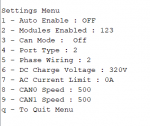
Updated Code 12/11/18

Have now worked my new found menu structure into this beauty.

https://github.com/tomdebree/Tesla-Charger/tree/master/Gen2TeslaChargerV2

-----------------------------------------------------------------------------


One thing to note is if the charger is acting up for some reason, unplug usb and power cycle the charger. The due sometimes likes to hang, this does not occur when no usb is attached.
 

Attachments

#601 ·
Nice one, good job.
Updated Code 12/11/18

Have now worked my new found menu structure into this beauty.

https://github.com/tomdebree/Tesla-Charger/tree/master/Gen2TeslaChargerV2

-----------------------------------------------------------------------------


One thing to note is if the charger is acting up for some reason, unplug usb and power cycle the charger. The due sometimes likes to hang, this does not occur when no usb is attached.
Sent from my LEX720 using Tapatalk