DIY Electric Car Forums banner

Tesla 10Kw Open Source Charger Controller

1 reading
130K views 645 replies 35 participants last post by  Kevin Sharpe  
#1 ·
So I've had a first look at the Tesla Gen 2 10Kw charger. Now , making one of these work as is with CAN messages is near on impossible due to the level of integration of the charger and the car. So I decided to have a look inside. Seems it uses 3 x 3.5kw modules linked back to a central logic board. Each modules connects to the logic pcb with 8 wires.

So far i have identified GND , +12v , +5v and a 500k canbus. Two lines seems to carry analog signals and one seems to be open circuit. Attached see some CAN captures from this internal network. I may be wrong but I bet it will be easier to work out these messages and get the individual charger modules to wake up.

So plan is to design a little breakout board so I can monitor the signals on a live car during the charge process and log the CAN messages.

Stay tuned:)
 

Attachments

#42 · (Edited)
I agree, that looks nicer and smoother than the previous guess of the first two bytes being a 16 bit integer in big endian. Attached is a PDF graphing both on top of each other. You can see that they match *very* closely but that the new 9 bit version is smoother. I also graphed byte 0 as it tracks the mains voltage pretty much exactly but with a small value. It doesn't appear to be current as it is constant when voltage is constant.

So, what does byte 0 encode anyway? Inquiring minds want to know!

Edit: Byte 0 is essentially the mains voltage / 9. Still no idea why it's there.
 

Attachments

#43 ·
Thanks Colin. Graph is very good. You can even see where I paused the variac on the way up and down. I got stuck working on the TM4 earlier in the year until I stopped thinking of CAN frames as bytes and more an array of bits then things made a lot more sense.

Not sure about byte 0. Perhaps something to do with the pfc booster? When I get a log from a charging car I hope this will make more sense.
 
#44 ·
One of my great failures in life has been not getting Savvycan to run on linux. So i'm stuck with windoze. Did a 4 hour round trip last night to log a charge session. Guess what this morning? Bill decides to take a crap on my laptop. No more log files:mad:

Did find one interesting thing which I noted. Seems messages 0x042c , 0x043c and 0x044c carry the charge current request in bytes 2 and 3 relevant to each power module. Was very easy to see on the live graphs. Anyway , more logging to be done.
 
#45 ·
One of my great failures in life has been not getting Savvycan to run on linux. So i'm stuck with windoze. Did a 4 hour round trip last night to log a charge session. Guess what this morning? Bill decides to take a crap on my laptop. No more log files:mad:
Well, previously it was kind of a pain to compile SavvyCAN as it had external dependencies that you had to compile first and then place in the proper place. Now it just requires QT. I think it's easier to compile everywhere now and I know a lot of people do compile it themselves on linux. There are just so many LINUX variations that it's hard to come up with one executable that runs everywhere. I've thought about statically compiling the executable so that it has less dynamic library links that could mess up. At any rate, if you have GCC and QT 5.9 installed in LINUX you should now be able to easily compile it yourself.

It sucks that you lost your log files. I've thought about maybe adding a feature to do streaming logging so that it directly logs to file, flushing maybe every couple of seconds so that the most you'd lose during a crash is the last few seconds of log. There's no technical reason why this feature couldn't be added.
 
#47 ·
Well, without the log I'm just shooting in the dark but what about bytes 3 and 4 in little endian? That gives you a value of 0xFE4A which is -438. If all three modules are providing a third of the output current each then you'd expect right around 4.2 amps each. So, -438 could be the current in hundredths of an amp or -4.38A for that module.

It makes sense to me anyway. Maybe it's right, maybe it's wrong.
 
#49 ·
One remark would be, why would a charger use a signed command?
Not like this charger is setup to do bidirectional.
You might think so but I've seen them do it. Probably to keep the values in sync with the rest of the vehicle. Usually positive current is discharge and negative current is charge. So, keeping the chargers in negative range makes them work the same way as everything else when it comes to current reporting.
 
#50 ·
Ok have a new log up on the github. Didn't want to upload a raw log as it's a friends car and I don't want him getting in trouble with Elon! This one is the 4 command messages from the charger logic board to the power modules :
Logic_msgs_chg_start.csv

Events:
start capture
press ‘open charge port’ button
get out of the car
insert plug
Charging initalises
Charging commences
stop capture


Oh and SavvyCAN now compiles and runs on Linux:D:D:D
 
#51 ·
Guess why we had the weird mains voltage /9 byte? Because I didn't ground the charger case during the test. Ground the charger case and they track. The damn thing is looking for an earth leak!!! It must have an earth leak detector built in!
 
#53 ·
Ground the charger case and they track. The damn thing is looking for an earth leak!!! It must have an earth leak detector built in!
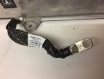
I guess that explains the heavy duty earth strap and is also something we need to look out for on the HVJB :cool:
 

Attachments

#57 ·
It's my guess that 0x42C controls the first module, 0x43C the second, and 0x44C the third. 0x45C is probably common to all three or something. If that guess is true then only the first module is getting activated so far. I'm not sure if that makes sense. 12.6A into a pack at 360v or so is 4.5kw which exceeds the rating of a single module. But, we don't know (or I don't know) the actual charge rate during this last log. It might not have been 12.6A. All I know is that you can see the charger ramp and then it stays constant but only in one message. As you said, the other two messages are the same but they don't seem to contain current requests in bytes 2-3 like the first message 0x42C does.

However, all three messages go through a pattern in bytes 0,1,4. It's always 0x42 in byte 0 for all three messages. Byte 1 starts out at 0x60 for all three. It then goes to 0xC4 for all three and at the same time. Byte 4 starts out as 0x64 for all three then transitions through 0x68 then 0x69 then 0x6D. The 0xC4 in byte 1 does not happen until byte 4 is 0x6D. We stay 0x6D for a bit then drop to 0x6C then go to 0xFC on all modules. Eventually 0x42C (first module???) goes to 0xFE in this byte. This seems to indicate that the module should be ready to start charging. About 8 seconds after the byte goes to 0xFE a charge ramp happens in bytes 2 and 3.

I'm attaching a graph that shows the charge ramp found in 0x42C bytes 2 and 3(little endian). Also in that graph is a mystery signal found in 0x45C bytes 0-1 which appears to be big endian and signed. It fairly closely matches the current ramp from 0x42C but it starts out hovering high and it goes negative for a little bit. I don't know what it means. Bytes 6-7 are similar to bytes 0-1 in 0x45C but they don't seem to quite make sense any way I try to graph them. Bytes 2-5 in 0x45C are fairly constant and I don't yet really have much of a guess at what they do.

But, to me it seems like the first three messages are commands and the fourth is a status feedback of some sort.
 

Attachments

#54 ·
That big strap connects to chassis? So how/where is chassis connected to earth ground? Does anyone have access to a Tesla to measure continuity between chassis and the ground terminal of the charge port?

During examination of Panasonic EVSE units i found that there is a deliberate leakage path from the mains line to the earth ground line that is used to detect a valid ground exists. It also has a ground-fault current detection circuit that uses a deliberate by-pass path to prove that the GFCD is working properly.

The Tesla EVSE might have similar checks but haven't examined one in person. Maybe those same checks are also done inside the Tesla chargers.
 
#56 ·
Put together a log with 0x042c: Phase 1 charger command, 0x207 and 0x227 which contain charger mains voltage, battery voltage and charge current for phase one.


Block1_start_charge_msgs.csv


Not had a chance yet to do a playback as will need to move operations to the shed and hook up to a 360v battery and some serious power.
 
#59 · (Edited)
Damien, what charger did you plug into?

Wallbox, type 2? Single phase 16A or three phase? Looks like the charger is being mind full of 16A AC current limit.

Looks like in 0x227 bye 4 (D5) and byte 5 (D6) are the current feedback, looks like DC current in mA.

Multiplying this with the battery voltage in the same message, 0x227 byte 2 (D3) and byte 3 (D4) it would give you power, however this seems to nude 3.7 Kw. I do not know if this would be unreasonable.

However it looks like as collin points out, 0x42C byte 2 (D3) and byte 3 (D4) contains a current demand, scaled a factor of 2.

Will do some more digging to find some more info, however a bench test will easily allow you to sus out a if the findings are true.

As Damien mentioned, treat the bytes as a row of binary.

Maybe these are just lucky numbers but, 0x42C 0x42 0xC4, if i take 0x2c4 I get 708, but you can trim the binary. 0010 1100 0100 to 010 1100 010 which is 354V or just about 3.7V per cell. But then again I might just be trying to make the numbers work.

AC current in 207 byte 5 (D6) and then bit 0 and 1 from byte 6 (D7) to make a 10bit integer, curve matches the dc current exactly, however it has a strange factor of 0.035amp per bit.
 
#60 ·
Damien, what charger did you plug into?

Wallbox, type 2? Single phase 16A or three phase? Looks like the charger is being mind full of 16A AC current limit.

Looks like in 0x227 bye 4 (D5) and byte 5 (D6) are the current feedback, looks like DC current in mA.

Multiplying this with the battery voltage in the same message, 0x227 byte 2 (D3) and byte 3 (D4) it would give you power, however this seems to nude 3.7 Kw. I do not know if this would be unreasonable.

However it looks like as collin points out, 0x42C byte 2 (D3) and byte 3 (D4) contains a current demand, scaled a factor of 2.
Yes, all that seems to check out. I've created a DBC file that allows one to graph and investigate the values and all of that looks good and proper.

As Damien mentioned, treat the bytes as a row of binary.

Maybe these are just lucky numbers but, 0x42C 0x42 0xC4, if i take 0x2c4 I get 708, but you can trim the binary. 0010 1100 0100 to 010 1100 010 which is 354V or just about 3.7V per cell. But then again I might just be trying to make the numbers work.

AC current in 207 byte 5 (D6) and then bit 0 and 1 from byte 6 (D7) to make a 10bit integer, curve matches the dc current exactly, however it has a strange factor of 0.035amp per bit.
I don't think that 0x42 0xC4 encodes the pack voltage. 354v doesn't match the voltage reported in 0x227 bytes 2 and 3. The way it progresses doesn't look right either. But, not every guess can turn out. History has shown all my wrong guesses - it's all part of the fun.

But, yeah, I think you might be correct about the AC Current in byte 5 and 6.

I'm attaching the DBC file. It should have all the best guesses so far.
 

Attachments

#62 · (Edited)
That explains why only one of the charger modules is coming on, plus it explains the 16A phase limit.

Would expect a 16A AC phase limit to be sent to the module, however scaling is weird.

I think that allot can now be sussed out playing it back to one module and varying our findings. Does it look like the message has a checksum?
 
#63 ·
There appear to be no checksums to me. Usually anytime there is a checksum you also have a counter in the frame somewhere. There are no counters I can see and nothing that appears to be a checksum.

The master board does send current commands to the three modules so I don't know whether there is any form of current limit per phase sent beside that. It might just be that the commands in 0x4?C don't go above what the power source can provide.

A kind of interesting quirk of international power is that, in the US, we almost always have 40 or 50A service anywhere there is 240v power. Only our 120V outlets are 15 or 20A fused. We basically only use 240V for dryers, stoves, heaters, etc so we need a lot of juice and thus the outlets are all 50A. As such, in the US I'd expect that a charger that detects 230V would try to turn at least two of the charge modules on and draw around 7kw. But, that's kind of irrelevant to the discussion. I just thought it was interesting.
 
#64 ·
I'll be back home at the weekend for some serious testing. Traveling most of the week. I have two wires from the control board to the power modules that seem to do nothing. I wonder do the modules get the pilot signal or perhaps a ttl version of it. If so they would each know the limit of current available. We also know they measure the mains voltage.

So if each module knew they had 16 amps then they might report it in a message. 0x207 byte 4 and bit 0 of byte 5 arranged as an unsigned 9 bit int and multiplied by 0.066 give me roughly 16 amps. applying the same scaling to byte 5 bits 1 to 7 and byte 6 bits 0 and 1 give some interesting numbers.But i'm probably just making the numbers fit.

I'll make up a fake pilot signal and see if I can make them throttle up and down.

I kinda think this will just work:) Has anyone tried this before by the way? bypassing the charger logic board I mean.
 
#70 ·
Yes those are the wires. I'm guessing around 16mm square. Maybe a little bigger. Was in an S70 recently supercharging at 250amps!

....not that I would have had something connected to the SWCAN or anything .....:D
 
#71 ·
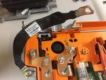
Latest Tesla part is a EU high voltage junction box. Interesting to see how they label the AC wires and deal with the 3 power module connection in the charger. Anyway, regular charger hacking resumes tomorrow:)
 

Attachments