DIY Electric Car Forums banner
61 - 80 of 646 Posts
Discussion starter · #61 ·
We used a 16A single phase evse. Measured 235v ac input under load.

Could 0xc4 be the mains voltage?

I'll be running some tests soon.
 
That explains why only one of the charger modules is coming on, plus it explains the 16A phase limit.

Would expect a 16A AC phase limit to be sent to the module, however scaling is weird.

I think that allot can now be sussed out playing it back to one module and varying our findings. Does it look like the message has a checksum?
There appear to be no checksums to me. Usually anytime there is a checksum you also have a counter in the frame somewhere. There are no counters I can see and nothing that appears to be a checksum.

The master board does send current commands to the three modules so I don't know whether there is any form of current limit per phase sent beside that. It might just be that the commands in 0x4?C don't go above what the power source can provide.

A kind of interesting quirk of international power is that, in the US, we almost always have 40 or 50A service anywhere there is 240v power. Only our 120V outlets are 15 or 20A fused. We basically only use 240V for dryers, stoves, heaters, etc so we need a lot of juice and thus the outlets are all 50A. As such, in the US I'd expect that a charger that detects 230V would try to turn at least two of the charge modules on and draw around 7kw. But, that's kind of irrelevant to the discussion. I just thought it was interesting.
 
Discussion starter · #64 ·
I'll be back home at the weekend for some serious testing. Traveling most of the week. I have two wires from the control board to the power modules that seem to do nothing. I wonder do the modules get the pilot signal or perhaps a ttl version of it. If so they would each know the limit of current available. We also know they measure the mains voltage.

So if each module knew they had 16 amps then they might report it in a message. 0x207 byte 4 and bit 0 of byte 5 arranged as an unsigned 9 bit int and multiplied by 0.066 give me roughly 16 amps. applying the same scaling to byte 5 bits 1 to 7 and byte 6 bits 0 and 1 give some interesting numbers.But i'm probably just making the numbers fit.

I'll make up a fake pilot signal and see if I can make them throttle up and down.

I kinda think this will just work:) Has anyone tried this before by the way? bypassing the charger logic board I mean.
 
Discussion starter · #66 ·
It may be better to pursue a method where the brain is completely replaced and you drive the power electronics directly.
That is what I (and Michal Elias) did with the Tesla inverter.
That's exactly what I'm doing:)
 
Discussion starter · #70 ·
Yes those are the wires. I'm guessing around 16mm square. Maybe a little bigger. Was in an S70 recently supercharging at 250amps!

....not that I would have had something connected to the SWCAN or anything .....:D
 
Discussion starter · #71 ·
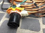
Latest Tesla part is a EU high voltage junction box. Interesting to see how they label the AC wires and deal with the 3 power module connection in the charger. Anyway, regular charger hacking resumes tomorrow:)
 

Attachments

Discussion starter · #76 ·
I got a few twitches out of the charge this morning but then the power went out due to a storm crossing over Ireland today:)

Something else different on the EU HVJB. See that box on the front with some of the orange charge leads going to it? I think this is how they switch between single and 3 phase charging. Will investigate tomorrow.
 
There is another difference in the power connections to the chargers. It could be that Damien's was set up for two chargers, mine only had one.

In my version there are two bundles of six wires to the charger. They ran from the AC Master and DC Master plugs (on the main board of the HVJB) directly to the master charger on one side of the HVJB. A pair of straight 6-to-6 connection.

Damien's EU HVJB shows a connection to both the master and slave charger sides of the HVJB. I was expecting there would be another pair of 6-to-6 connections from the AC Slave and DC Slave plugs, but the cables suggest something different.

The differences could be a combination of EU and Single/Dual charges?

Jeff
 
Discussion starter · #80 ·
Ended up running my house for over 24 hours from batteries. Mains came back on this evening and I got the charger setup in the workshop feeding the test pack. These power modules are interesting beasts in themselves. They have their own built in HV precharge and main relay. So far if I dump the can capture into the module it precharges , closes the relay then faults out before delivering current. Going to get deeper into it tomorrow and see what I can find.....
 

Attachments

61 - 80 of 646 Posts