DIY Electric Car Forums banner

Tesla 10Kw Open Source Charger Controller

3 reading
130K views 645 replies 35 participants last post by  Kevin Sharpe  
#1 ·
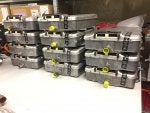
So I've had a first look at the Tesla Gen 2 10Kw charger. Now , making one of these work as is with CAN messages is near on impossible due to the level of integration of the charger and the car. So I decided to have a look inside. Seems it uses 3 x 3.5kw modules linked back to a central logic board. Each modules connects to the logic pcb with 8 wires.

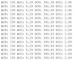
So far i have identified GND , +12v , +5v and a 500k canbus. Two lines seems to carry analog signals and one seems to be open circuit. Attached see some CAN captures from this internal network. I may be wrong but I bet it will be easier to work out these messages and get the individual charger modules to wake up.

So plan is to design a little breakout board so I can monitor the signals on a live car during the charge process and log the CAN messages.

Stay tuned:)
 

Attachments

#140 ·
Hello recorded a quick video yesterday. (Will upload later today)Unfortunately since I am at a family member house a few hours a day it's not as detailed as I wish. But wanted to chime in and let you guys know.that I figured out the pinout for the front contactor board of the 72 amp gen 3 charger. Working now on replaying Damien can messages to trigger one of the phases to output DC. Also working on creating a python file or Wireshark with all can messages we figured out so far and their format..
I also have a few can captures I am trying to get not sure how useful those would be.
 
#142 ·
Haven't gotten around to replaying the captures. Will try playing the arduino sketch tonight. One reason why It may not work is that I have the control board still connected to all phases. Unless I cut the traces on the different phases PCB for can messages. It may cause interference or mixed messages to be sent. I will playback some captures to the phase if I can find a tool and convert the capture files to canplayer. I have saavvycan installed but the can messages are not the same format afaik.

I also compiled a excel with all can ids I seen from all captures (both mine and damien) and which fields are always the same. The idea is to make a python file that would alert when a can message has a value in a field we always seen as zero. (or different static values before)
 
#144 ·
Don't forget you will have both a wake-up and phase enable line to pull high if it is like the gen 2.
Yup, I believe pin 8 (the one besides the 5v for the MCU) on the phases appears to be a enable signal going up to around 2.3v before the charger phase times out.

unfortunately, a coworker is using my lab PSU will see if I can get another one.

I also found out that the 0x54X and 0x10x canids appear to be either a boot progress message or a count up until disabling the phases/failing. They always count till 0x32FF and once they reach 0x32FF they shut down.

Considering they never appear to show up for a successful charge session can capture I tend to think they are timeout messages.

I made a python application to find anomalies in values the idea is that it notifies when it notices a pattern (data) on a can id we never seen before and prints the timestamp/message for figuring out what special did I do while charging it. (for example unplug one of the fuses of one of the phases while the other ones are charging)

Will work tonight on running the arduino sketch using a chipkit cmod and can breakout I have. (no due)

Bonus Video:
 
#146 ·
#148 ·
I connected a raspberry pi with a MCP2551 and MCP2515 and the linux mcp251x kernel driver.
The CANH and CANL are connected to the pin 5 (can L and pin 6can H ) on the third phase.
Since all 3 phases share the canbus it does not make a difference which phase is the can connected too.
The control board of the charger is still in place and powered up.

Bought up the can0 interface on linux/debian and ran the candump -L command

You can replay this file back on any linux machine over a virtual can
Code:
modprobe vcan
sudo ip link add vcan0 type vcan
sudo ip link set vcan0 up
Afterwards if you would like to replay the traffic you can run the canplayer command using the following line

Code:
canplayer vcan0=can0 < candump-ac119-dc-46.83-internal-controlboard.log
This will send the recorded can0 to the virtual vcan0 interface on the system
At this point I can open any linux can tool that supports socketcan and read the data. (later on I will try Savvycan)
 
#156 ·
Took a look and the rear has a header on a 90 degree angle smd soldered on the control board and thru hole on the charger phase. I was thinking of trying to remove all the solder from the thru hole and insert plastic or something to isolate the pin from the copper will give that a try later.

I finally got power back here in Puerto Rico that should speed things up a bit.

Also have we found the canids for the temperature sensors? I found 2 NTC on the boards of the gen 3 charger was thinking of sticking the soldering iron or a heatgun on them and see which can id starts changing.
 
#161 · (Edited)
Is this correct?
It's not giving me correct values with my 46.83v DC pack.
it's giving me for voltage 4359 and for current 53740

Code:
elif message_id == 0x220:
                        dc_voltage = (recv_message.data[3] * 256) + recv_message.data[2]
                        dc_current = (recv_message.data[5] * 256) + recv_message.data[4]
Message should be 227

Code:
      case 0x227: //dc feedback
      dccur = frame.data.bytes[7]*256+frame.data.bytes[6];
      dcvolt = frame.data.bytes[3]*256+frame.data.bytes[2];
      newframe = newframe | 2;
      break;

     Serial.print("  DC voltage : ");
     Serial.print(dcvolt/100,2);
     Serial.print("  DC current : ");
     Serial.print(dccur/1000,2);
And again, scaling can be off as i have not validated it. But its always good to start with nice looking numbers and then tweak it.
 

Attachments

#158 · (Edited)
If we are talking about a second-generation inverter, then I managed to get more or less acceptable results in this way:
Code:
switch(frame->id){
	#ifdef START_A
		case 0x207:
		getACVoltageA =  frame->data.bytes[1];
		getACCurrentA = (frame->data.bytes[6] * 256 + frame->data.bytes[5]) / 29.0;
		break;
		case 0x227:
		getDCVoltageA = (frame->data.bytes[3] * 256 + frame->data.bytes[2]) / 94.0;
		getDCCurrentA = (frame->data.bytes[5] * 256 + frame->data.bytes[4]) / 1200.0;
		break;
	#endif
	#ifdef START_B
 

Attachments

#165 ·
bublik, a gen 2 charger?
Yes

What you using to control it?
ArduinoDUE)

have you found away to limit the AC current draw? Because that is one of the last things to figure out, for when you are charging off a limited supply.
0x042c
frame.data.bytes[2]
frame.data.bytes[3]
Here, the limit of the current consumption by the AС is established

Cool:) Any pictures ?
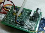
pictures will be tomorrow) today only this ...

Forgive me for possible misunderstandings) Google translated) is not all clear and answer, too, through Google-translator ...
 

Attachments

#213 ·
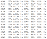
Any ideas what this means?

My phase 2 module is still fighting. I can ramp 1 and 3 up and down all day. Either something is special about the middle module (doubt it) or I have a faulty charger. Has anyone managed to run all three modules and willing to share?