DIY Electric Car Forums banner

Tesla 10Kw Open Source Charger Controller

3 reading
130K views 645 replies 35 participants last post by  Kevin Sharpe  
#1 ·
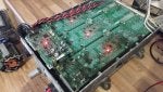
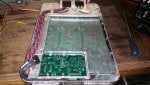
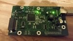
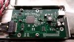
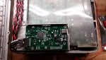
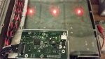
So I've had a first look at the Tesla Gen 2 10Kw charger. Now , making one of these work as is with CAN messages is near on impossible due to the level of integration of the charger and the car. So I decided to have a look inside. Seems it uses 3 x 3.5kw modules linked back to a central logic board. Each modules connects to the logic pcb with 8 wires.

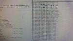
So far i have identified GND , +12v , +5v and a 500k canbus. Two lines seems to carry analog signals and one seems to be open circuit. Attached see some CAN captures from this internal network. I may be wrong but I bet it will be easier to work out these messages and get the individual charger modules to wake up.

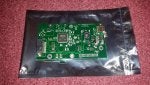
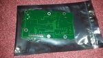
So plan is to design a little breakout board so I can monitor the signals on a live car during the charge process and log the CAN messages.

Stay tuned:)
 

Attachments

#183 ·
That's awesome. Keep up the good work! I've been following this thread for a while. Wish I had been able to developed my programming and communication skills but I am stuck in electrical and electronics.
 
#185 ·
woot great news damien.

on my end I finally got the Gen 3 charger wired up and it's now reading the DC voltage correctly. So the can messages appear to be the same format from Gen2. Next step will be to cut the traces to the Phase Control board and replay the arduino Tom File to see if I can charge my battery pack.

Will do later today and let you guys know if it also works.
 
#186 ·
Hooked up a charger board on usb and loaded blink. To my utter surprise it worked:)

Nice work annerajb. Keep us posted. Don't forget you have about a 1 second window to connect mains AC at the right time in the CAN capture. Any earlier or later and it won't start charging.
 

Attachments

#189 ·
I finally had time to cut the traces on one of the phases, Hook up a few wires and play around with the enable lines and the lab power supply.
Manage to turn it on by itself without the control board bugging me.
Gonna see if tonight I can start sending it the control commands for a charge from the arduino files.

 
#196 ·
Wish I had one of those chargers, or any of the tesla stuff besides a battery.

Love to contribute for sure.

Let me know if you want some features made that dont require testing?

For example writing the votalge and current setpoint to flash once you programmed it.

This way it will boot and start charging if 12V is present and we can have it command the charges only when AC is detected.
 
#197 ·
Thanks Tom. Sadly, genius here forgot to add an eeprom chip to this version of the board so the set points will need to be in the program. Will add to next rev.

The charger is a bit weird in that if ac is present before it asks for it it will fault out.
 
#201 ·
It doesn't exactly. But, you can write to the FLASH memory from within the program. This can be used as a form of data memory. However, unfortunately all of FLASH is zapped at once when you flash a new program to it so if you use FLASH memory it'll get zapped each and every time you upload a new program to it. That's SUPER annoying hence the use of an EEPROM chip.

The whole chip erase is more of a design issue with BOSSAC than anything else. If you wrote your own firmware updater it could rewrite only portions of FLASH and thus allow other parts to be used for storage. But, even then, the SAM3X has an erase pin and we all tend to expose it somewhere on the PCB. If someone pushes that button it's lights out for your stored settings in FLASH.