

Chevy Volt drivetrain


I actually bought the entire EV drivetrain from a 2013 Chevy volt with 7k miles. After 3 attempts of buying a new volt battery (paying for, waiting months, and then getting a refund from the dealer) I just went with a scrapyard unit. A few weeks ago I started tearing apart the Chevy volt pack and video taped the tear down and here are the links:
https://www.youtube.com/watch?v=00tTckGUv7I&list=UU1haWsGv-HcI10lapf4MBgg
https://www.youtube.com/watch?v=00tTckGUv7I&list=UU1haWsGv-HcI10lapf4MBgg
It's my first time shooting and editing video so future videos should be better quality
Here is a picture of the drivetrain sitting next to our daily driver volt (30,000 EV miles and going strong):
https://www.youtube.com/watch?v=00tTckGUv7I&list=UU1haWsGv-HcI10lapf4MBgg
https://www.youtube.com/watch?v=00tTckGUv7I&list=UU1haWsGv-HcI10lapf4MBgg
It's my first time shooting and editing video so future videos should be better quality
Here is a picture of the drivetrain sitting next to our daily driver volt (30,000 EV miles and going strong):
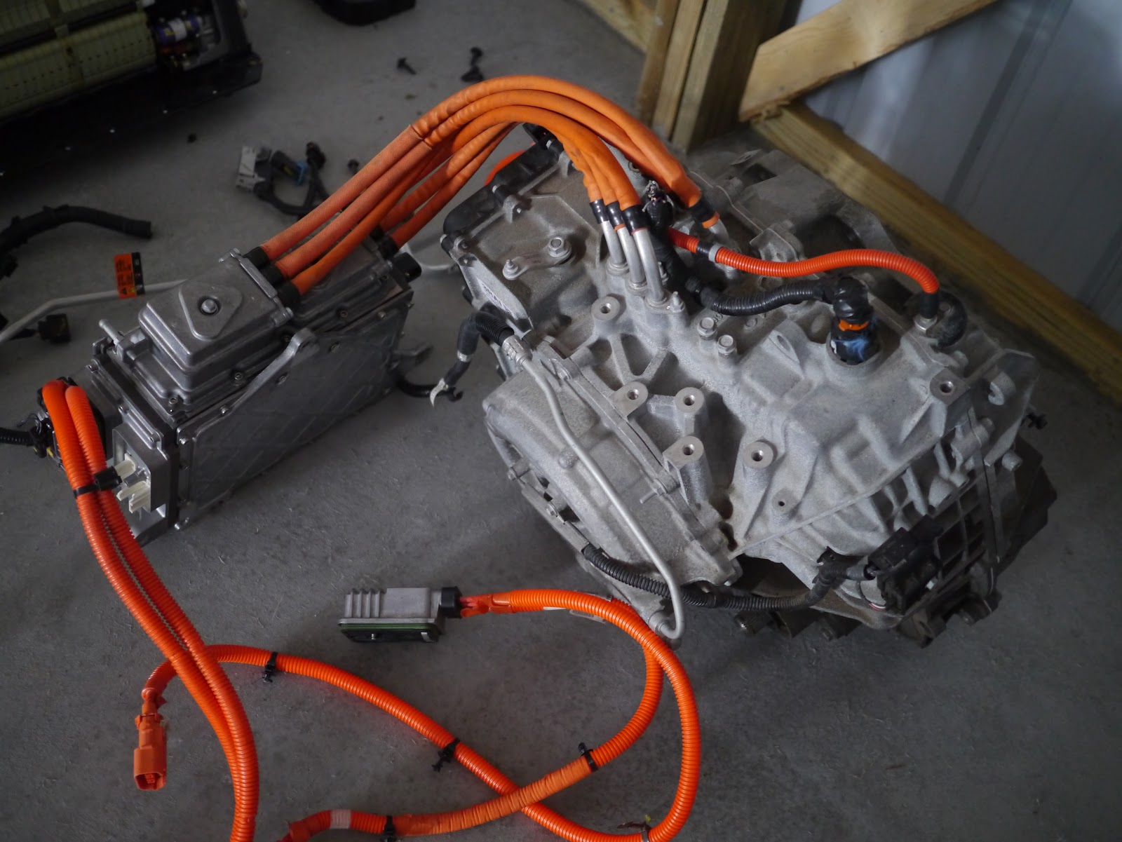
When I bought all the parts I made sure to get all the important wiring bits.
For those that don't know, the motor and inverter are very interesting, the motor is actually 2 motors. One is nested inside the other in a coaxial configuration and the inverter is actually two in one as well. It will take quite a bit of work to figure out how to talk to the inverter and very likely outside my capabilities (I am a ME not a EE for a reason ") . But a 111kW AC drive system for well under $1000 is a big opportunity for the DIY community.
. But a 111kW AC drive system for well under $1000 is a big opportunity for the DIY community.
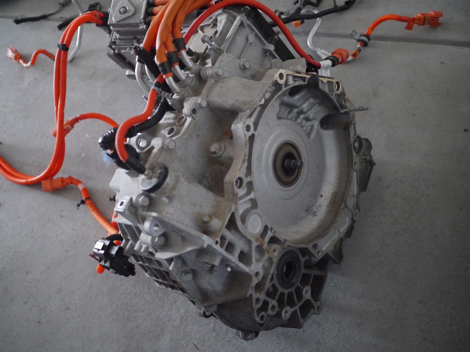
. But a 111kW AC drive system for well under $1000 is a big opportunity for the DIY community.Here is the engine side of the gear box. And on the bottom you can also see where the passenger side axle shaft comes out:
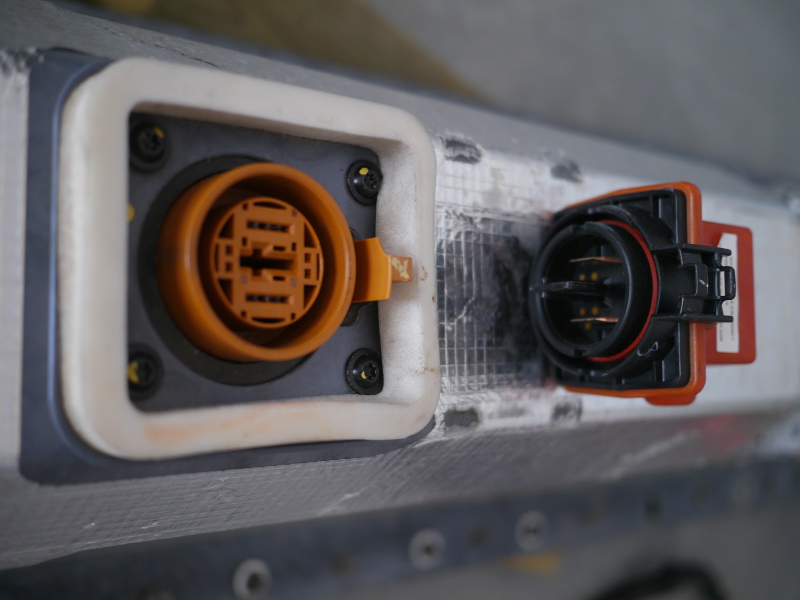
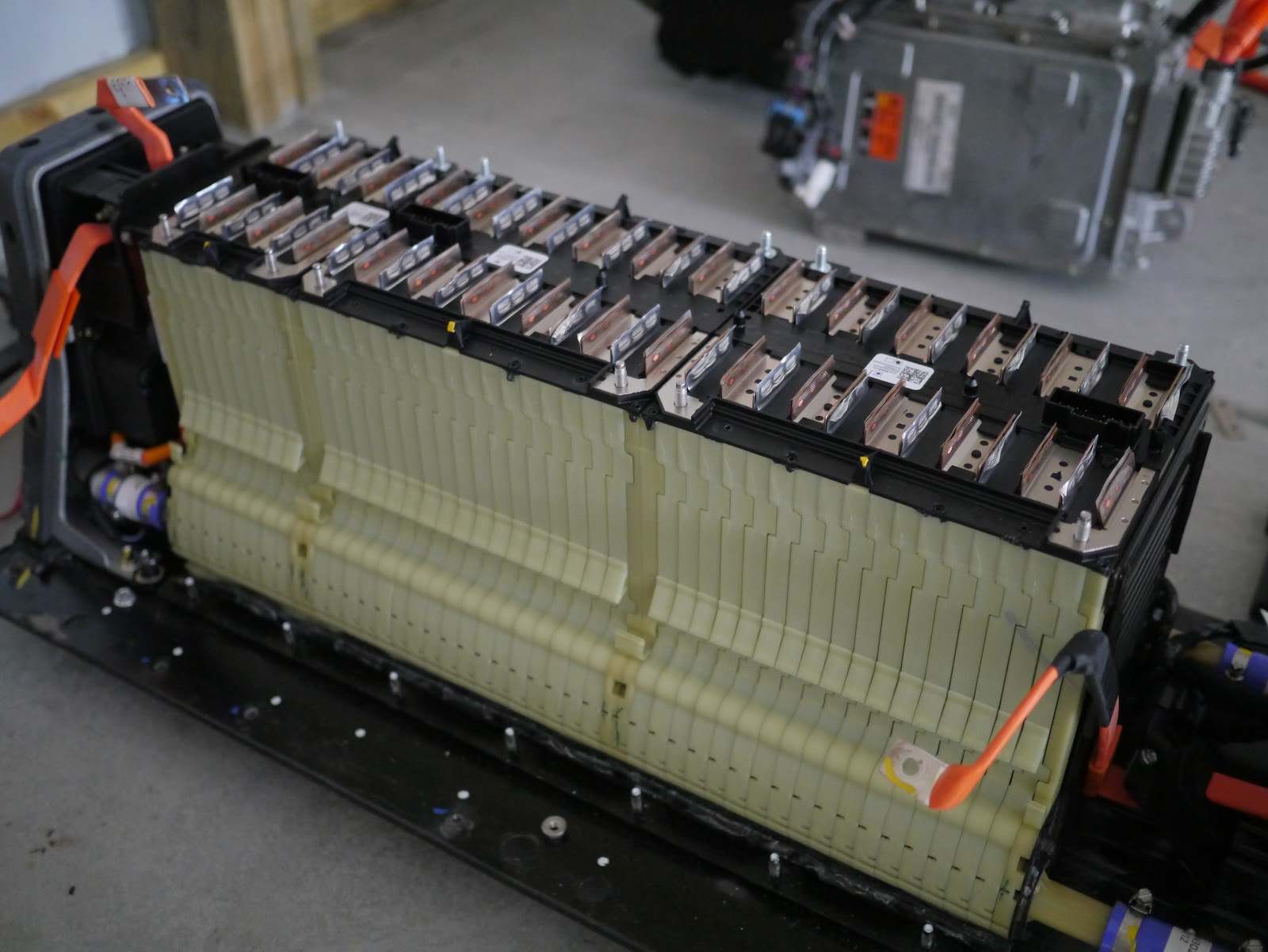
The Volt pack has a disconnect mounted on top. It is not the easiest to pull but I am pretty sure it is fused.
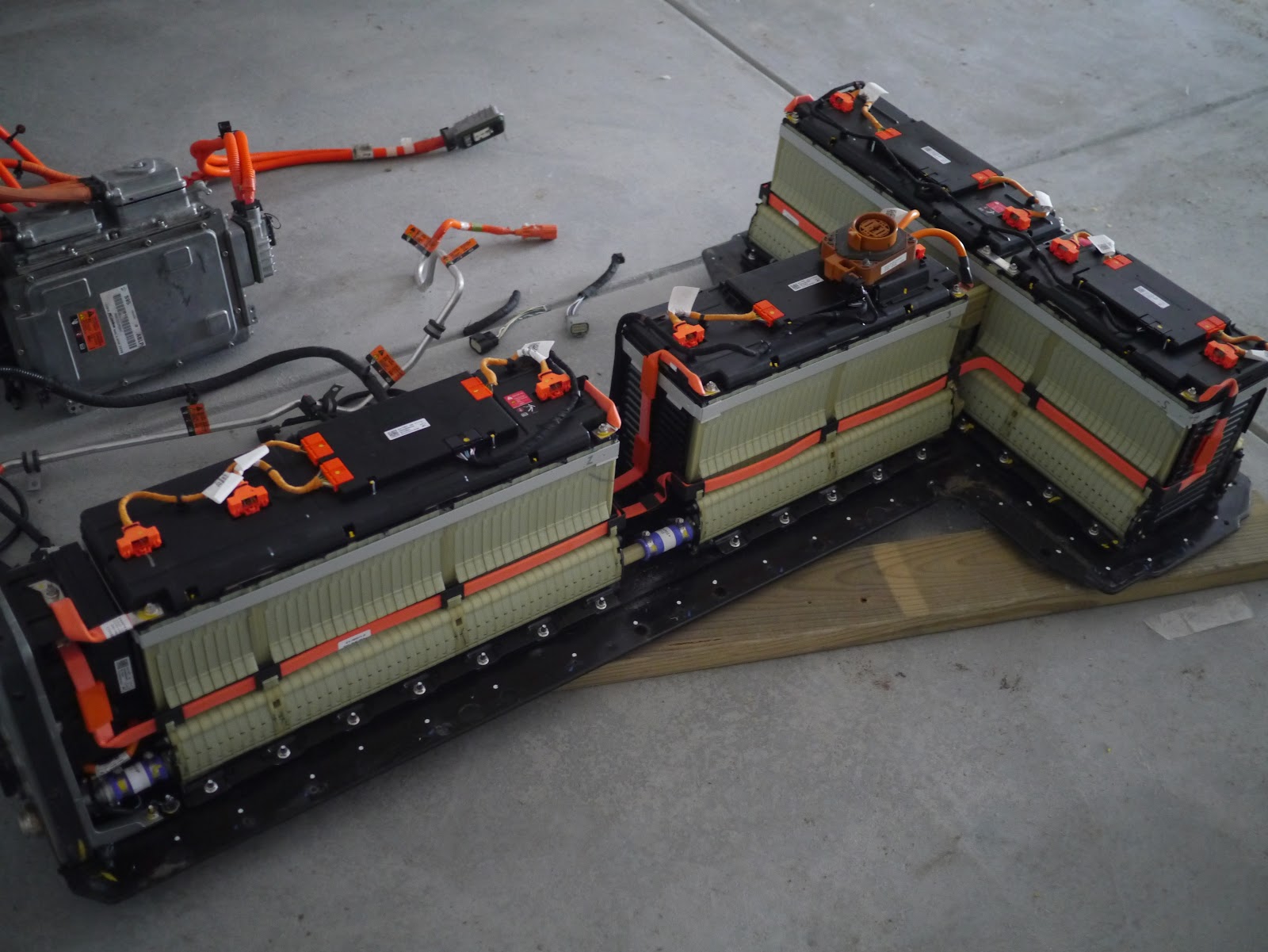
The pack cover is easily removed and the the whole pack is easy and straight forward to work on.
The pack is configured in 3 modules that are made up of 48V and 24V modules. The pack measured 370VDC total and is likely near a "full" charge. Keep in mind that chevy's version of a full charge is actually 80% SOC.
I took video of the whole process and will post it up on youtube once I get it all edited. The modules are pretty easy to breakdown and I will upload the pics from that process next week.


