DIY Electric Car Forums banner

BMS design guidelines

70K views 137 replies 19 participants last post by  patrick@drm.ch  
#1 · (Edited)
I think this forum is still lacking a definite thread for guidelines designing a BMS, whether commercial or just DIY for one's own use.

I was replying to http://www.diyelectriccar.com/forum...s/showthread.php/estimate-bms-cost-per-lithium-batteryi-p339260.html#post339260 but thought it would be off-topic, hence this new thread. So here's what I was going to reply...


BMS is simple as hell. Don't overengineer it.

IMHO, think about redistributive balancing only if you are going to mix variety of cells with varying specifications or quality.

Do a careful top-balance manually; let the BMS shunting take care of minor imbalance caused by self discharge and peukert effects, which are both almost nonexistent in all li-ion.

Recovering shunting energy is easy, I have built some prototypes (of bi-directional flyback transformer construction), but still, the amount of energy wasted there is so tiny... Does it make sense to do active balancing when using new, identical li-ion cells?

I would consider pointing all design efforts towards reliability, and key to reliability is in simplicity and careful consideration of all possible use & misuse cases. Look at the MiniBMS; they have a long thread on this forum where they share the schematic. It's important to take a look at how they solve design challenges for maximum simplicity, reliability and minimum cost in mind.

IMO, one MCU per cell is a good idea. Pick an MCU that has an integrated temperature sensor and you get an extra feature for free.

Implement:

- Low voltage shutdown for motor controller
- High voltage shutdown for charger
- Low voltage shutdown for charger (do not allow charging damaged cells). This is especially important for LiCoO2.
- High temperature shutdown for both motor & charger
- Low temperature charging disable/limiter (jeffcoat)
- Error & statistics reporting

Also:
- Make sure that no error condition such as
- full battery pack voltage over the cell module terminals
- short circuit on cell module
would cause excessive heat on the module,

- Make sure ALL error conditions cause shutdown for motor controller and charger.

- Add DC rated fuse
- make sure that it will blow before the shunt MOSFET & resistor get too hot in case of latch-on fault.

- For any problem you are going to solve by adding a new feature, make sure this problem really exists, measure and analyze it.

I'm thinking about compiling a small guide or "FAQ" on BMS design points. So any additions to this list are very welcome. I'll start by editing this list to add new points.
 
#3 ·
Siwastaja,
Have you taken a peak at this:
http://www.amazon.com/Battery-Management-Systems-Large-Lithium/dp/1608071049

Click on "search inside book" on the left under the picture of the book. Some great info. Goes over all the different designs. Sitting on my shelf if you want me to look anything up for ya.


Having the charger on at a low current at that low temperature could actually keep the batteries from freezing.
 
#7 ·
Thanks for starting this thread. The book on Amazon looks very good, and I see that the author is Davide Andrea of Elithion LLC. Having a comprehensive book such as this can be valuable, although in the electronics field the material can quickly become outdated. How much has changed since 2010, when it was published? And it was probably mostly written in 2008-2009.

Another good source of information is companies who make batteries and those who offer ICs for various aspects of battery management. Some such sources are:
http://www.linear.com/products/battery_management
http://www.maximintegrated.com/products/power/battery_management/
http://www.ti.com/lit/sg/slyt420/slyt420.pdf
http://liionbms.com/php/index.php (Elithion)
http://www.microchip.com/stellent/idcplg?IdcService=SS_GET_PAGE&nodeId=2087
http://www.freescale.com/webapp/sps/site/taxonomy.jsp?code=BATTMNGT
http://minibms.mybigcommerce.com/

I have several ideas which may be realized as separate designs or combined into a complete system
  1. A simple single cell monitor which presents a minimal current drain (10-100 uA) and flashes one or more LEDs showing SOC based on cell voltage from 2V to 5V. Target cost < $5/cell.
  2. Single cell monitor and charge/discharge controller. Flashing LEDs for indication of SOC. Bypass charge current upon maximum voltage. Isolated signal to charger to taper off charge and shut down when all cells fully charged and balanced. Open cell detection and protection: For charging by shunting charge current and sending shutoff signal to charger. For discharging avoid cell reversal by detecting low voltage and activating bypass circuit, and/or using power diode, and sending shutoff signal to controller and main interlock. Target cost < $10/cell.
  3. Single cell analyzer, which can perform a pre-programmed sequence of charging and discharging at various rates and store data or send to PC via USB connection for further analysis. Test profile can also be changed and controlled by USB. Target cost $50-$200 depending on cell A-h rating and complexity of software.
  4. Integrated modular battery pack for small cylindrical cells. Package 12 cells in series for 38.4V Li-Ion or 44.4V LiFePO4. Internal relay disconnects module under internal fault conditions, and requires external 12V signal to activate. Eight modules in series supplies 307V or 355V for 230 VAC VFD, or 15 in series for 576V or 666V for 460 VAC VFD. Modules may be connected in series or parallel for various voltage and current capacity.
Those are my ideas at this time. I want to do some testing on the inexpensive Li-Ion 18650 cells I found, as well as the NiMH which may be a viable alternative. Another version of these devices could be made for 12V SLAs and Flooded Lead batteries. My particular immediate interest is for use in small vehicles such as lawn tractors, wheelchairs, ATVs, and bikes, but may be scaled up for larger lithium cells of 20-100+ Ah capacity for road vehicles such as cars and trucks. I am focusing on standard industrial 3 phase motors so the battery pack voltage will be 300-600 VDC nominal, and 2-5 HP motors drawing 3 to 10 amps where one or two strings of 3600 Ah cells would be sufficient.
 
#8 ·
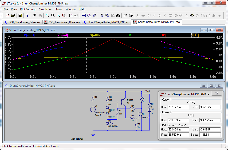
Here is a very simple and cheap single cell BMS which uses only about $3 in components and can be adjusted to limit charge to any voltage from about 3V to 4.5V. Here it is set to 3.62 volts.

Image


The functionality of the circuit could be replicated with much higher accuracy using a small PIC, with little difference in cost, and it can have a better SOC indicator and shutdown signal. The ASC file for this design is available at: http://enginuitysystems.com/pix/ShuntChargeLimiter_NMOS_PNP.asc
 
#9 ·
Consider what will happen to your $5 BMS if the cell it is connected to goes open circuit, either from internal failure, or because one of the terminal bolts loosened up...

To protect against this all-too-common failure mode requires adding either a blocking diode or a DC fuse capable of withstanding the full pack voltage. Both solutions are sub-optimal: the diode will result in a temperature and current dependent offset in the cell voltage while HV DC fuses are big and expensive.
 
#10 · (Edited)
Tesseract - is that not a problem with pretty much any of the commonly used BMS?

Do you have a better solution?

I guess you could use small PTC heater elements instead of the shunt resistors. They will get up to a pre-defined temperature and only sink the current required to maintain it. So even with the full pack voltage across it, the current is controlled and they will not spontaneously combust like a resistor!

Si
 
#12 ·
Tesseract - is that not a problem with pretty much any of the commonly used BMS?

Do you have a better solution?
No I don't have a better solution, and I consider this problem to be intractable when real-world economics are factored in. That is to say, it can't be solved without costing more money than consumers are willing to pay.

I guess you could use small PTC heater elements instead of the shunt resistors.... i
Nope. The PTC resistor has to be rated for the full pack voltage.
 
#11 ·
For the simple circuit I show above, during charging, if a cell opens up, the voltage is held at about 4 volts and the shunt resistor and MOSFET draw up to 20A. This voltage would be maintained as long as the charger were properly current limited, and of course this would be a fault condition which would be detected by the BMS (assuming it uses a PIC or other processor), and it would signal the charger to disconnect within 100 mSec or so.

In the case of a 150V pack with a 1 ohm (150A) load, the MOSFET reverse diode would conduct, and the 0.2 ohm shunt resistor would limit the current to 130 amps and there would be -27V across the cell BMS. The resistor would dissipate 3000 watts and the MOSFET would see 143 watts. But it would be easy to add an optoisolator so that any reverse voltage would turn it on and send a signal to the main interlock contactor to shut down. This would happen as soon as the voltage reached about -3V, at which point the shunt resistor saw about 12 amps which would be 28 watts, and the MOSFET would see 9 watts. If the cell opened gradually (as in 100 mSec or so), the voltage would rise slowly enough for the fault protection circuitry to shut down the pack before severe damage (or any danage) would occur.

Another safeguard would be a TVS diode across each cell that would limit the voltage to 6 volts or so. Here is a 3000W TVS that can withstand a pulse current of 326 amps and costs less than $1.
http://www.mouser.com/ProductDetail...ductDetail/Littelfuse/SMDJ50CA/?qs=sGAEpiMZZMsYiK5PgaDog9xriego/BKRX2LxccMvWjs=

Or a 5000W version that can handle over 500A for about $2 in quantity:
http://www.mouser.com/ProductDetail...ctDetail/Littelfuse/5KP50A/?qs=sGAEpiMZZMsYiK5PgaDog38p0a8Da%2bhYvYJr%2bz8m5XI=

A 3.5 volt version may be better:
http://www.mouser.com/ProductDetail...ProductDetail/Bourns/SMLJ20A/?qs=sGAEpiMZZMsYiK5PgaDogyJ4ny/JxXeZY8cFkHLu%2blg=

What happens when a cell opens without any BMS or other form of protection? Or with a commercially available BMS?
 
#13 ·
Perhaps a 5.1 volt zener and a fuse could handle both open circuit and short circuit. The zener would be in parallel with the reg and the the fuse would be in series those. In the event of an open cell while driving the zener would conduct for only a fraction of a second, but a longer fraction of a second than the fuse would remain intact. In the event of a open circuit while charging the diode would conduct at about 1 volt and the fuse blow. Here is an idea for the fuse. It gets trickier to find a inexpensive fuse with a higher DC voltage rating as the desired current gets higher. Very little shunt current should be required if you start with a top balanced pack.
 
#19 ·
... Here is an idea for the fuse....
The Cooper Bussmann BK-PCx series fuses are a pretty good choice here, with the caveat that low amperage fuses tend to fail early from vibration/fatigue in automotive applications.

Aside from that, the only real problem is that they are relatively expensive, ranging in price from $1.55 to $6.10 each in 100s. Hence my earlier comment about there being no solution to the open-cell failure problem which is economically viable.

In the end, the least expensive and most reliable way to protect a non-balancing BMS (ie - one that only monitors cell voltage) is with a series diode rated for more than the full pack voltage, accepting that the forward voltage drop of the diode will vary with temperature (and current, hence why I say to only use it with a BMonS) and that variation can only be partially compensated for in software (or hardware, if you are into a strictly analog solution).
 
#14 · (Edited)
The only way I can see to protect against an open cell is to detect it quickly and shut down the charger or the pack main contactor if it opens while the vehicle is operating. For the small battery packs that I am considering for tractors and such, with pack "modules" of perhaps 12 cells in series, it would be fairly easy to use a wired-OR configuration of optoisolators which would turn on in the case of an overvoltage event due to opening of any single cell, and it could trip a relay that would disconnect the entire module. My idea is to require an external 12V (or higher) signal to activate the pack, and it could even latch on using the pack voltage to keep it closed. It would draw some current from the pack, but a relay with a 24 VDC coil with contacts rated at 30 amps has a coil resistance of 660 ohms for 36 mA and probably can be held in using a PWM circuit with about 10 mA, which would be less than 1% reduction of capacity for a pack rated at 3600 mA or higher.
http://www.mouser.com/ProductDetail...TE-Connectivity/T90N1D42-24-01/?qs=sGAEpiMZZMtSzCF3XBhmW6vMa/MpJxoPyldbPKvob5Q=

This particular relay costs about $2 in quantity and can switch 30A at 28VDC or 240 VAC. Since the pack will have a BMS with 11 good batteries at 3.3V each and one open cell with a reverse voltage of -6V or less, the relay would actually only switch about 28VDC, especially if there were more than one series string in the battery pack. This would isolate the string and allow the others to provide enough continued capacity to operate the vehicle at reduced power.

Another way to handle an open cell would be for the relay to be an SPDT type which would open the path to the defective cell and shunt the rest of the current, which would just diminish the pack voltage by 3 volts or so. For a 150V pack with multiple strings in parallel this would only be a loss of 2% of full pack voltage and the current draw would still be fairly well balanced. If the packs were isolated with high current Schottky rectifiers it would avoid the problem of the higher voltage pack trying to charge the lower voltage pack, but unless the cells were fully charged it would probably soon balance itself even without diodes.

BTW, the fuse you suggest is only rated up to 5 amps, and costs about $3, which is more than the 30A relay I mention:
http://www.mouser.com/ProductDetail...ProductDetail/Cooper-Bussmann/BK-PCI-5-R/?qs=sGAEpiMZZMtLo%2bUrTGGA8ZHRY8wA6WCm
 
#16 ·
BTW, the fuse you suggest is only rated up to 5 amps, and costs about $3, which is more than the 30A relay I mention:
http://www.mouser.com/ProductDetail...ProductDetail/Cooper-Bussmann/BK-PCI-5-R/?qs=sGAEpiMZZMtLo%2bUrTGGA8ZHRY8wA6WCm
You shouldn't need to bypass much current. I have seen no need to bypass more than 1/2 amp (EVpower regs) with a pre-balanced pack. I was eying a 2 amp fuse for about a 1.5 amp shunt.

What impressed me about the fuse I listed was the DC interrupt rating. Up to 450 volts DC with up to a 5900 amp interrupt. They where listed for $2.17 each at Digi-Key. If an inexpensive zener that will hold on longer than the fuse is available it would be a few extra dollars a cell.

There have been some BMS systems that drain a cell dead without warning if subjected to brief reversals or over-voltage conditions. I was thinking in terms of shutting the cell module down dead so so the monitoring loop would throw an error. There may be simpler, even passive, to provide that kind of protection against over voltage and reverse voltage.
 
#15 ·
I just found this resource that seems rather comprehensive and worthwhile looking at. I found it when searching for "open cell protection lithium battery pack EV".

http://www.nfpa.org/assets/files/PDF/Research/RFLithiumIonBatteriesHazard.pdf

Some other links with useful info:

http://www.o2micro.com/prods/o2m_intbattery_catalog.pdf
http://www.ipd.anl.gov/anlpubs/2011/10/71302.pdf
http://www.ibt-power.com/Battery_packs/Li_Ion/Lithium_ion_tech.html
http://www.eosenergystorage.com/documents/2012_JES_Christensen_Kojic_Critical_Review_Li-air.pdf (Lithium-Air cells)
http://www.batteryspace.com/prod-specs/6059.pdf (testing)
http://industrial.panasonic.com/www-data/pdf/ACI4000/ACI4000PE5.pdf
http://www.transportation.anl.gov/b..._conference/docs/battery testing roundtable/battery_mgmt_system_tsinghua_lu.pdf
http://www.mpoweruk.com/protection.htm (also many other topics)
http://www.transportation.anl.gov/pdfs/TA/149.pdf (costs)
http://www-scf.usc.edu/~rzhao/LFP_study.pdf
http://www.evolveelectrics.com/Lithiumate_Lite.html (Elithion BMS)
http://www.te.com/content/dam/te/gl...nglish/products/Circuit-Protection/knowledge-center/documents/mhp-techpaper.pdf
http://www.nrel.gov/vehiclesandfuels/energystorage/pdfs/apesaran.pdf (thermal issues)
http://www.batteryfaq.net/battery-news/how-much-do-you-know-batterys-protection-circuits-1056.html
http://ecec.mne.psu.edu/Pubs/2006-Smith-JPS-1.pdf (power and thermal)

and the list goes on. There is a huge amount of information out there, but really not very much specifically addressing the problem of open cell failure. :eek:
 
#17 ·
I think the 1/2 amp bypass specification is only for charge equalization, where it removes, say, 5% of total charge current of 10 amps until other cells with greater capacity reach maximum SOC. But if a cell opens, with a constant current source, there will be a voltage imposed on the open cell which will be the full charger compliance voltage less the voltage of the intact cells. So a battery charger which uses a 170 VDC peak voltage (from a 120 VAC rectified line voltage), on a 120V nominal pack with 38 cells at 3.2V each, will have 170-(37*3.2) = 51.6V applied to it. If the rest of the pack cells have internal resistance of 0.05 ohms (probably much less), it only takes 20*1.9 = 38 VDC to maintain a 10 amp charge.

The situation is much more dire in the case of discharge during maximum current draw, where the entire remaining pack voltage can be applied to the open cell, and the inductance of the motor could generate a much higher voltage. So it is important to have a fast passive means to maintain continuity of the circuit during fault conditions, long enough for a secondary means of shutdown can be activated.

As I explained before, having multiple strings of cells in parallel eliminates most of the problem by providing auxiliary paths for the current, and a simple disconnect of a defective string, or bypass of an open cell, can permit continued use of the EV until the defective cell can be replaced.
 
#18 · (Edited)
the balance circuit that i have passes a certain % of current based on how unbalanced that cell is from the rest of the pack. costs about $1 - $1.50 per cell if the parts are bought in bulk.

so PStechpaul is talking about passing current when the max voltage has been reached? or just a maximum safety voltage thingy?

And dont tell me that the mainstream dc motors that we DIY's buy dont have feedback protection? (as PStechpaul metions above)
 
#20 ·
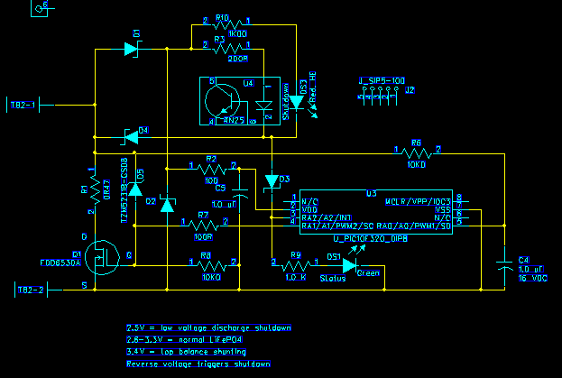
I have made an initial design of a single cell BMS system:

Image


It has a shunt MOSFET and a 0.47 ohm power resistor which is designed to limit charging voltage to a voltage determined by the PIC, and it can shunt up to 7 amps before the voltage will climb above 3.3 volts. The top balance voltage can be programmed to anything from 3V to 4.5V, and at that point it will start shunting the charge current and also will activate the optoisolator which can shut down the charger. It is possible to connect the optoisolator outputs in series so that shutdown will occur only when all cells have been balanced, or if connected in parallel the first cell to reach maximum voltage will shut down the charge. There is also a visual indication from the red LED. :D

If a reverse voltage is applied, as may happen if a cell is depleted during discharge, the MOSFET reverse diode will conduct and the current will be shunted by the 0.47 ohm resistor. It will also activate the optoisolator which should be connected so as to shut down the pack. Of course, in normal operation, the PIC would sense a drop in cell voltage before reversal occurred, and it would flag the error and shut down. But in case of a sudden open circuit of a cell, it would also protect the system by limiting the voltage. :)

The green LED is used as a status indicator. It can be set up to flash at a variable rate to indicate battery voltage. Thus during charging it can show the progress as the voltage increases, or it can also use the time elapsed as a measure of SOC. This design does not have a current sensor, so it cannot comput Ah, but that is more a function of the charger. ;)

In the absense of charging current, the PIC is powered from the cell, and can provide a flashing green LED signal to indicate open circuit voltage. The PIC itself draws only about 25 uA when operating and as little as 20 nA standby. The LED is visible at current as low as 2 mA and it can have a duty cycle of 100 mSec/10 sec which is the equivalent of 20 uA. So an average draw of 50 uA on a 3 Ah battery would drain it to 90% capacity in 6000 hours. It could also be programmed to enter standby mode if the open cell voltage was less than, say, 2.8 volts, so it would not deplete the battery even after years of storage. :)

The total cost of this design is mostly the PIC ($0.50), MOSFET ($0.75), Optoisolator ($0.25), and power resistor ($0.50). The other components are mostly penny and nickle parts or maybe $0.25 total, and the PCB would be about $1 in 100pc quantity. So about $3.25 total. Of course this is designed for a small pack of 3-10 Ah capacity, but the design could be scaled up to handle 40-200 Ah cells. :cool:

This is still in its "infancy" so it may change as I dig into details. Also I have chosen the smallest and cheapest PIC I could find, just to see if it could work, and I have a couple of development boards using this part. A more capable part with more I/O pins would still be less than $1. I also need to deal with the problem of reading the cell voltage which will be the same as or greater than the supply voltage. A voltage divider would be the obvious answer, but the ADC requires a maximum source impedance of 10kohms, which would be 320 uA on a 3.2 volt cell. Probably still OK. But I could use an external MOSFET to connect the ground side of the divider only during measurement. Such things are part of the challenge and allure of electronic design. So please tell me any pros and cons of this circuit, and any features that might be desired. ;)

Thanks.:)
 
#23 ·
Good ideas.

(1) There could be separate charging and discharging modes. When charging, the main problem will be overvoltage, and it does not matter if the optoisolator draws 5 mA from the charger. So the optoisolator outputs will be wired in series and must be ON for the charger to be enabled. The bypass will start at the rated top balance voltage (3.4 to 3.5V) and the charger will only be disabled if any cell exceeds 3.6 or 3.7V. It could also be a fault condition if a cell is less than, say, 2.5V. This would be almost automatic since the forward voltage of the optoisolator LED and perhaps a series diode would turn it off at about that voltage.

(2) In discharge mode, the 5 mA current draw is insignificant as long as the pack is being used, which can be determined by detecting normal rise and fall of cell voltage from delivering current to the controller or from regeneration. During discharge, shutdown would only be needed for a low cell voltage. There could be a time delay to allow for short bursts of high current during acceleration. As in charge mode, the optoisolator would shut down anyway at about 2V. If a longer time delay is needed, a capacitor could hold the PIC supply voltage above 3V for 1 or 2 seconds.

(3) The PIC has a built-in temperature sensor, so it could detect an abnormally high temperature of the cell and/or the shunt resistor. It could also adjust the threshold voltages depending on cell temperature.

(4) It seems like the charge and discharge modes can be just about the same, and the normally ON shutdown signal can be used for either. If no change is detected after 15 minutes it could go into standby mode where it could wake up every minute to take a voltage sample. That would require the watchdog timer to be running while asleep, but that takes only about 500 nA.

Thanks for the suggestions! :)
 
#24 ·
OK, I made some changes that should make this work:

Image


I added a Schottky diode across the battery which will be more effective at limiting reverse voltage to about 0.5V. But it may not be necessary. The Overvoltage LED DS2 automatically limits the cell voltage to about 3.8 VDC even without the PIC. This also may not be necessary.

Otherwise, as long as there is at least 2.5 VDC for the PIC, it will be operational, and the internal reference of 2.048V will be available, and the voltage divider will provide 1/3 battery voltage to the ADC. It presents 15k impedance or about 213 uA drain on the battery. When the voltage is within normal range, RA2 will be held low which activates the optoisolator and lights the green LED. When the voltage reaches the 3.4V top balance voltage, the output of RA1 will start to turn on the MOSFET which will shunt some of the charge current. It is a PWM output so it can provide a variable voltage to control the MOSFET. A capacitor on the gate provides a smooth DC, but it is also possile to use PWM without the capacitor to reduce power in the MOSFET.

If a fault condition is detected, the output of RA2 will go high which turns off the optoisolator and turns on the red LED.

When no change is sensed over a 15 minute interval the device will enter a sleep mode which turns off the LEDs. This would occur when the system is neither being charged nor providing current. It would still draw current through the voltage divider, but even that could be turned off if a small MOSFET were added to the ground leg, and turned off during sleep. That would require another I/O pin, which can be provided with another PIC.

I think this thing is ready to be built and tested. :)
 
#26 ·
why have you got 2 diodes in parallel?
That is a center tap dual diode in TO-220 package. I have a bunch of them. It may not even be needed if the BMS detects a low cell and shuts off the controller. Otherwise it needs to handle full pack current.

Also what is JP1 and JP2?
Those are jumpers that need to be removed for programming the PIC using in circuit programming, which is through the five pin header J2.

I have updated the schematic to make it a bit clearer. What do you think?
 
#28 ·
The circuit I show is designed to provide top charge management as well as in-use protection during discharge, and also as a single cell status indicator with minimal current draw. The idea is to have one of these on each cell, and when a pack is connected to a charger (or the controller in an EV), the optoisolators will be connected in series and function as a fault protection interlock.

The maximum number of cells would be that required for a 360V or 720V pack for use with a commercial 230 or 460 volt VFD. So for LiFePO4 (3.2V) it would be 112 or 224, and for Li-Ion (3.7V) it would be 98 or 196. It may be possible to tell the charger what the total pack voltage at maximum charge should be, by adding a 36 ohm or 42 ohm resistor to each optoisolator, so that the charger can inject a 10 mA signal to the string and it should read 360 or 420 mV per cell, corresponding to 3.6 or 4.2 volts per cell. So a 112 cell LiFePO4 pack would read 112*0.36 or 40.3V, while the 196 cell Li-Ion pack would read 82.3V. The saturation voltage of the optoisolator transistors would add another 200-300mV per cell, but it could be calculated by sampling at two different currents. For instance, with the optoisolator LED at 5 mA, a 5 mA collector current causes a 600 mV drop, while a 2.5 mA current causes a 200 mV drop. So the apparent resistance due to the saturation voltage changes from 120 ohms to 80 ohms, while the actual resistance will stay at 36 or 42 ohms. This might not be practical, but it's just an idea to consider. Maybe a diode would be better, since it has a fairly predictable forward drop if you know the temperature, and it is about 600-800 mV.

There are more sophisticated ways to communicate between the charger or controller and the battery pack, of course. The usual BMS reads perhaps 16 cells, so a 720V pack could be handled by 12 BMS units. They could be connected by means of isolated transmit and receive USARTs where each BMS has a unique address and thus each may be queried for information as well as controlled by the motor controller or the charger. That could even be done with up to 255 devices with unique 8 bit addresses.

Probably best to use the KISS principle, however. :D
 
#29 ·
I have 108 CALB60 that I currently have the miniBMS on. The miniBMS does most of what I want, but it doesn't let me know WHICH cell has gone soft. If you could figure out a way to signal this (via LED) or via the master, that would be great - I would be willing to be a Scratch Monkey for this project.

Cheers, Peter
 
#32 · (Edited)
Thanks for the additional information. What conditions would be necessary to determine that a cell is "soft"? I had thought that the open circuit voltage gave some indication, but perhaps it needs to be under some sort of load. It is certainly possible for the single cell BMS that I am designing, to apply the shunt load (in this case 0.47 ohms) to the cell (about 6 amps at 3 volts), long enough to take a voltage reading under load. Hopefully this would be able to trigger the fault indicator which would open the output of the optoisolator.

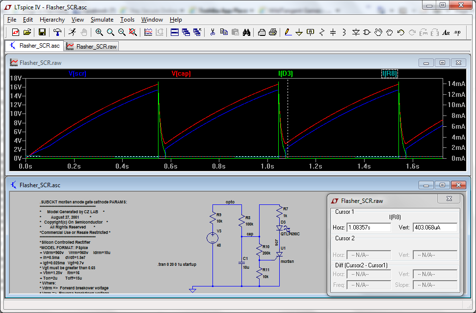
To display the open circuit condition of the optoisolator of a bad cell, I would use an LED flasher as I mentioned above. It can be made from a Diac, but also from an SCR. I just happen to have several thousand SCRs I got surplus, which are 2N6504, rated 50V and 25A. I'm not sure they would work, but I found a SPICE model for a similar SCR, MCR8SN, and it seems to work well enough in simulation:


Image


It shows a fairly bright 14mA pulse through the LED at a rate of about twice a second. If this will work for the MIniBMS, it should be easy enough to build a prototype circuit to see if it works. This simulation uses a 48V supply with a 10k resistor as a nominal 5mA signal for the BMS master. When the opto is open, as shown, this circuit draws only about 400 uA.

Unfortunately, the 2N6504 requires about 10mA gate trigger current compared to 25uA for the MCR8S. There is a 2N5064 sensitive gate SCR in a TO-92 package rated at 800 mA with 200uA(max) trigger current, and it's only $0.16/100. I am ordering a few to try. There's also a BT150 in a TO220 package rated at 4A with a 15uA gate, or $0.60/1 and $0.46/100.

The 2N6027 PUT is only $0.16 that may work at a low voltage (about 6V). The Diac takes about 30V and costs more. But it could be combined with the 2N6504 to make a high power flasher.

Whereabouts in San Diego are you? It's been over ten years since I last visited, and when I have, I stayed in Ocean Beach, which is a really cool place similar to the more local Rehoboth Beach. I've also explored the San Gabriel mountains (Mt Wilson Observatory), Pacific Crest Trail, Old Town, Balboa Park, Tecate (Mexico), and Torrey Pines. I wouldn't mind taking another trip out that way sometime. :)
 
#33 ·
In order to determine which battery is soft, it has to be done under a load. I'm sure this is covered in other threads, so I won't toss out any (mis)information I may have.

I live near the football stadium, not near the beach (much to my regret - I used to live near the beach in Santa Cruz).

So once the cell BMS has discovered that a battery is soft, how will this be communicated to the head unit? Have you figured out how to get communications to work in noisy EM environments?

Cheers, Peter
 
#34 ·
The head unit will see the open optoisolator in the series string as a drop in current, which will disconnect the charger or adjust the throttle (which is how the MiniBMS works). You would have to look at the LEDs on the cells to determine which one is bad and then remove it for repair or replacement. The LEDs could be mounted remotely but you would need one wire for each cell.

To implement a more sophisticated intercell communication system, my idea is to equip each cell monitor with an isolated receiver and transmitter. Actually only the receiver needs to be isolated. I might use a high speed optocoupler such as the HCPL-0302 or a digital isolator such as the SI8421. They are about $1 each. But a simple optotransistor such as the PS2561, which I'm already using, is only about $0.20 each and with 3-5 uSec rise/fall times it should be able to handle communication at 38k bps. :)

What I would do is connect the master unit's transmitter to the receiver of the first cell monitor, and then daisy chain them with transmitter to receiver. The transmitter of the last unit would have its transmitter connected to the receiver of the master. The master can send a coded signal initially that will request the devices to "enumerate", where the first device assigns itself an address of "001", and then sends the command to the next, which assigns itself as "002". When these messages have propagated to the last unit (in your case #108), it will send its signal back to the master, which would then know that there are 108 units. :cool:

The master may query any unit by sending a message with its unique address and a command, which would be acted upon and an acknowledgement would be sent on down the chain back to the master. An individual unit may also send an alarm signal down the chain which will eventually arrive at the master for processing. The total propagation time for a 4 byte data packet at 38k through 108 units is a little over 1 mSec, so there is no major timing issue. :)

There are PICs available with everything needed to implement this communication function and many other tasks, for less than $1 each. For instance, the PIC16F1823, which is a 14 pin device. I already have a couple of a similar PIC16F1825 and its 8 pin cousin the PIC16F1822, which are only a little more expensive. If this works as I expect, it should be relatively immune to the EMI environment. It may even be possible to use fiber optics for the data connections, but that can get pricey. ;)
 
#35 ·
But a simple optotransistor such as the PS2561, which I'm already using, is only about $0.20 each and with 3-5 uSec rise/fall times it should be able to handle communication at 38k bps. :)
$0.20 is pretty cheap but still not zero. Voltage difference between two cells is just few volts so it's possible to use a simple capacitor to isolate the BMSs. In my miniBMS I'm using such an approach. Communication is like PStechPaul described. I use ATTiny45 which is just $0.60 per unit with a temperature sensor on board and ability to work from 2.7V to 6V. Total cost around $2 including PCB
 
#38 ·
I thought you meant the miniBMS that is commercially available at www.cleanpowerauto.com. It's probably best not to use that name, as it may be a registered trademark. Maybe MicroBMS? ;)

I also found your thread about using IR for communication. It may be a good idea, but I think it may be complicated if you have multiple emitters and receivers, and it may require some power and could be expensive. Maybe using fiber optic coupling? I think wire coupling with an optoisolator may be the easiest and most reliable. Actually, just one wire could be used. It would connect to a resistor and an open collector driver to the cell (-) of the first module, and the second module would already have a connection to the first cell (+) which connects to the second cell (-). So that connection will drive the LED of the optoisolator of the receiving module. :cool:

That will be for an "enhanced" design, and I'll post a schematic for my concept soon. For now I want to make a prototype of my simpler concept which will just perform top charge balancing and overall shutdown (with flashing LED indication) when any cell is determined to be faulty or "weak". It could be set up so that on power-up, and on external reset, it will perform a load test on the cell by activating the bypass limiter and taking a reading which can be compared to the open circuit reading. It could do this for a quick test in a few mSec so the battery drain will be insignificant, even with a test current of 6 amps. :D

Would you be willing to post your schematic so we can discuss any pros and cons of your design? I showed you mine, so now show me yours! :p
 
#39 ·
I thought you meant the miniBMS that is commercially available at www.cleanpowerauto.com. It's probably best not to use that name, as it may be a registered trademark. Maybe MicroBMS? ;)
Good idea, Thanks :)

I also found your thread about using IR for communication. It may be a good idea, but I think it may be complicated if you have multiple emitters and receivers, and it may require some power and could be expensive.
This is not my idea, and as you I was concerning about it. However I thought about the solution:) Multiple emitters is not a problem. I had designed some IRDA devices and know how to deal with it. Power is not a problem too. We have a lot Ah:) Moisture and dust is my concern. Water could be unbreakable obstacles for IR. Also I wanted to split batteries for few banks. How to communicate in this case. Than's why I've decided to go with a wire
 
#42 ·
OK, looks simple enough. The devil is in the coding, eh!

One thing I see as a problem is the IRF7821 MOSFET which really needs 4.5V for the gate, although the curves show minimal operation at 2.5V. But the power supply for the ATTiny is two diode drops below the battery voltage, which may be as low as 3.3 volts during charging, so there might not be enough to turn the device on. A better choice may be the FDS6574A which only costs a little more and is fully characterized for 2.5V gate drive and even 1.8V.
http://www.mouser.com/ProductDetail...child-Semiconductor/FDS6574A/?qs=/ha2pyFaduif3b3oZ1SEUSUGF2A22InXhJ4m%2b8Xho0I=

If you can accommodate a TO-252 package you can use FDD6530A which can handle 21 amps and 33 watts and is about $0.50/100:
http://www.mouser.com/ProductDetail...child-Semiconductor/FDD6530A/?qs=sGAEpiMZZMsrr1kXJis%2bJ24zftF0OaFr5mFNqfcVECA=

Otherwise it looks OK, although I question what C2 is for? And when you send signals through the capacitors of the uplink, there will be transients that exceed the power supply rails, so there should be some protection for the uC input. ;)

Looking forward to your test results when you get your PCBs! :)
 
#43 ·
OK, looks simple enough. The devil is in the coding, eh!

One thing I see as a problem is the IRF7821 MOSFET which really needs 4.5V for the gate, although the curves show minimal operation at 2.5V.
Yes, you are right. But as I said, this is a draft. I put the IRF for PCB design only.

I question what C2 is for? And when you send signals through the capacitors of the uplink, there will be transients that exceed the power supply rails, so there should be some protection for the uC input.
This is a trick :) All modules have C2 and don't have T1, R6 and R1. So all of them including a "host" can communicate through LINKs. If you don't have a host, you can connect a relay to an open connector. In this case the very first module should have T1, R6 and R1 but C2 removed. Then the devil in the coding will do everything else :D
 
#44 ·
I scanned through the specs of the AVR ATtiny, and it has some nice features. The ADC can be configured as differential input with an optional x20 gain element that would make it easy to read 0-50 mV for current measurement with a shunt. The internal selectable voltage reference is good, and it seems to have a very capable PWM generator. It might be possible to use the SPI system for the communications. The Microchip products have similar capabilities, and I will stay with those since I'm more familiar with the architecture and code and programming tools.
 
#45 ·
I made a more detailed and updated schematic showing the connection for two cells. I was able to find a way to use the little PIC10F320 to provide cell to cell communication so a master unit can query each cell and take action accordingly. So it looks like a BMS can be built for about $3.00/cell and $50 for a master controller which can shut down the charger or throttle back the motor to protect weak cells or to perform top (or bottom) balancing. It also has a temperature sensor for each cell, and it has EEPROM to store calibration constants or cell history. I figure it can operate with an average current of several hundred microamps and provide shunt current top balancing up to five amps or so, and also bottom balancing if so desired.

http://enginuitysystems.com/files/BMS.pdf
 
#46 ·
I made a more detailed and updated schematic showing the connection for two cells. I was able to find a way to use the little PIC10F320 to provide cell to cell communication so a master unit can query each cell and take action accordingly. So it looks like a BMS can be built for about $3.00/cell and $50 for a master controller which can shut down the charger or throttle back the motor to protect weak cells or to perform top (or bottom) balancing. It also has a temperature sensor for each cell, and it has EEPROM to store calibration constants or cell history. I figure it can operate with an average current of several hundred microamps and provide shunt current top balancing up to five amps or so, and also bottom balancing if so desired.
Few questions:
1. What is purpose of D1 connected in parallel to MOSFET? Revers connect protection? It looks like a firework :D It will burn immediately in reverse connection. Also Q1 has an embedded diode and you'll get 8A in this case.
2. What is purpose of C1 47uF?
3. VSS is not connected to GND. U1 will not work
 
#49 ·
This BMS is initially intended for use with my tractor project, which will use 320 or 640 VDC and a VFD and at most a 5 HP (3.7 kW) motor, so current will be about 20-30 amps maximum. For higher power applications, I am considering the option of having multiple 10 or 20 Ah 320 or 640 VDC packs in parallel with separate BMS functions for each string. This has the advantage that a failure of one cell in a string can just result in taking out that string, so the others can provide continued power. It could be disconnected with a fairly small relay without danger of arcing contact damage because the other packs will keep the voltage at a minimal value and it won't be much current because the other packs will be providing that.

I was not sure if a true PWM would be OK for charging bypass. It would consist of alternately bypassing about 7 amps and allowing full charge current through the cell at the top balance voltage. The average current would be reduced and the average cell voltage would be also reduced, but the peaks might be higher than optimum. Also, the MOSFET can dissipate 20W so it could supplement the power of the resistor. But probably cheaper to use a higher power resistor and use true PWM.