DIY Electric Car Forums banner
61 - 80 of 138 Posts
Smpavlik,
I'm curious if you have heard of anyone using capacitor coupled communication in an EV? The reason I ask is that there is a lot of noise on the battery pack coming from the charger and controller and I always wondered if it would be possible to use capacitive isolation for communication on a battery pack.
I didn't hear about that but did some experiments in noisy environment. You are right, capacitive isolation is not the best way but it's possible. I wait for PCB and shortly will do the experiment.
 
Make sure ALL error conditions cause shutdown for motor controller and charger.
Image
Yes, that is the idea. The only thing that this BMS does not have is a current monitor, which should be the responsibility of the charger or controller. It could be incorporated in the master unit, perhaps, as an auxiliary measurement for redundancy.

My idea for multiple high voltage packs in parallel would allow for a small relay to open on a series string as long as the other parallel strings keep the voltage fairly constant. This could be accomplished by having a fairly large capacitor across the series string. Thus if a relay opened a pack it would not see the entire pack voltage and the capacitor would handle the current of the load or the charger long enough for the contacts to be fully open.

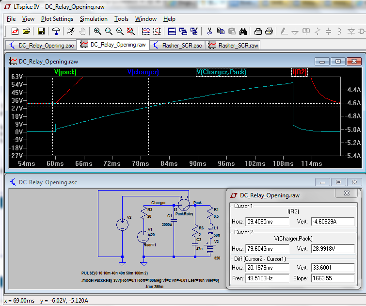
Here is the idea, showing what would happen if a 5 amp charger with 420V capability was disconnected from a 320V battery pack by a relay. Note that the voltage on the relay contacts rises slowly so that at 20 mSec (a typical opening time), the contacts have less than 30VDC on them. After that, it would rise to 100V in this case, but by that time the connection is fully open and the contacts only need to withstand the DC voltage:

Image


BTW, your jpgs should be gifs:
Image
 
My idea for multiple high voltage packs in parallel would allow for a small relay to open on a series string as long as the other parallel strings keep the voltage fairly constant. This could be accomplished by having a fairly large capacitor across the series string. Thus if a relay opened a pack it would not see the entire pack voltage and the capacitor would handle the current of the load or the charger long enough for the contacts to be fully open.
I don't really understand you proposal. Why do you need to disconnect battery strips separately? And if you really want this, how do you connect the stripes to a motor?
Batteries can be connected in series and then the strips connected in parallel; or connect batteries in parallel and then connect the packs in series. The last variant is widely used in laptops. No need to tell that all batteries must have same capacity and BMS is a must.
 
My idea is to be able to have multiple battery modules, complete with BMS protection, with an internal relay or contactor to disconnect the internal batteries from the external connections in case of fault. It could also be set up so that the contactor would be open until an external signal were applied, so that the module would be safe to handle. This would also provide the safety factor desired in case of accident, in which case all of the modules would be shut down and the risk of contacting high voltage by occupants or first responders would be minimized. ;)

The concept of multiple high voltage modules in parallel also provides redundancy, where the failure of any pack would not totally disable the vehicle. And it allows for the augmentation of the battery kWh by simply adding modules in parallel as needed. :)

The modules would have internal sensors to determine if there is one or more batteries externally connected and energized, and would allow activation in parallel only if the external voltage is close to its own voltage. Each pack could also have a series diode which would eliminate high current charging of a weak pack with a stronger one, as is the case with direct parallel connection. With the diode on a 160V pack, its forward drop would be less than 1 volt at normal current draw of 10-20 amps, which is less than 1% of capacity. It is also possible to make an active synchronous rectifier with MOSFETs, where the voltage drop is dependent only on the RdsOn, which can be 10 milliohms or so for only 100-200 mV drop. Such a solid state switching device could also replace an electromechanical contactor for pack protection, and since it can switch much faster, it would be suitable for DC. :)

If such modules can be made for easy replacement in an EV, it would even make it possible to have precharged modules available at refueling stations. The concept would be similar to trade-in propane tanks. Since the batteries are subject to aging, each pack could contain a charge/discharge counter and a real time clock, which could be read and the cost of a replacement pack could be adjusted by the differential between the new pack and the old. ;)

I think I've strayed a bit off-topic, and perhaps this would be worth a separate thread. But it's also what I see as a logical extension of the BMS concept and would make the protection independent of external components. It could also possibly incorporate a charging module so that all you need to do is connect the pack to a 120/240 VAC line. :cool:
 
Understand. Actually I thought about a multi-pack battery but moved the idea to a position #8 in my list :D
One thing that you are right is this should be a separate thread and discussion should be very detailed. For example 10-20 amps load is not a common use case. It should be hundreds amps and this is different story
 
I built a single cell management module using the PIC10F322 development board. I found that the ADC has only 8 bits resolution. and although the chip has an internal reference, it can only be read by the ADC, which uses Vdd as its reference. This is actually a handy feature, since the Vdd is the battery voltage I want to measure, so if I measure the internal 2.048V reference, I can determine the Vdd voltage by using the formula (for the high limit): 2.048*256/4.2 = 125. I think I will need to use a more capable unit for the final product. The PIC12F1822 has everything I need in an 8 pin package and still costs only about $1. Here's a video:

 
I want to share my recent finding on my infrared BMS.

So the infrared communication itself: its slow, about 2000 to 3000 bits per second. Each data packet is about 100 bits, so the round trip time for 20 modules (120 cells) would be 1s. I'm using a FEC code on each value (not the entire packet!) that can correct a 1-bit error and detect a 2-bit error (Extended Hamming 16/11 code)

The voltage sensing: as to not waste energy in voltage dividers I wanted to find out how far you can take it. I ended up with 10M/1.5M on the 6th cell and accordingly lower values on the other cells. Each input is buffered with a 1nF cap.
Every channel is sampled about 150 times per second in Atmels ADC noise reduction mode (shuts off most of the MCU to reduce switching noise). Every sample is fed to an IIR filter. The output of the IIR filter is transmitted on request. During transmission no A/D conversion is done because the transmission causes significant noise.

Here is the result of a long term test I ran last night:

Image


The cells are top balanced and floating at 3.34V according to my voltmeter. As you can see, 4 channels do not have any error, channel 3 is constantly offset by 0.01V (might be a rounding error) and channel 6 (the one with the highest input resistance) has a glitch of 0.06V after 2h.

Then I placed the pack outside for it to cool down and then placed it in the oven for a temperature test:

Image


Image


Channel 1 is not affected by the temperature, channel 2 is affected a bit, channels 3-5 seem to have some sort of temperature coefficient and channel 6 is happily moving about. But still, the largest error is still only 0.06V

I don't quite understand why it works so well, but I have some theories:
- The ADC is designed for 15kSMPS at an input resistance of 10k
- While sampling it has an input resistance between 1k and 100k in series with 14pF
- The leakage current is at most 0.01µA
-> I underclock it at 16 kHz for at most 1kSMPS
-> I excessively filter the values
-> I buffer the input with a cap, making it slow but stable
-> I use noise reduction mode

In former experiments I used the internal band gap reference to compensate for supply voltage swings. Turns out the bandgap reference is more unstable itself at temperature changes than the supply voltage, so I ditched that.
 
The results look pretty good. If you have a 10 bit ADC and a 5 volt reference, your resolution will be 5/1024 = 0.005V, so anything more than 0.01V variance must be due to other effects. With a high impedance voltage divider, RFI may be a problem, and it could be power line noise of 50/60 Hz. One way to remove this is to use a sampling rate of 300 per second which is 5 samples per cycle at 60 Hz and 6 samples per cycle at 50 Hz. If you sample at that rate for 100 mSec (30 samples) it will read 6 cycles at 60 Hz or 5 cycles at 50 Hz. The integral number of cycles cancels out the power line noise. If you are using 150 samples/sec it will also be effective. You will have 5 or 6 samples per half-cycle which is still OK.

You can also get more effective resolution by adding the 30 samples for a total of 30720 counts which will have a resolution of 162 uV. Accuracy will still be limited to the reference and the 10 bits of the ADC, but it might result in less "jitter".

Of course, the high impedance divider may limit how quickly you can perform conversions. The 10M/1.5M for the 6th cell converts 3.6*6=21.6V by a factor of 1.5/11.5 to 2.817V. The 1nF makes a time constant of about 0.0015 seconds and for 1% settling (5 TC) it is 7.5 mSec. This may pose a problem for high sampling rates, especially if the readings vary greatly. But if the readings are all about the same, the sampling capacitor in the ADC will already be at about the same voltage so it will not draw much current from the external 1 nF capacitor.

I am not really familiar with IIR filters per se, although I know about some of the examples, such as Butterworth. Here is an explanation for anyone else: http://en.wikipedia.org/wiki/Infinite_impulse_response

Something else to consider is how you are measuring the individual cell voltages. Cell #1 is measured directly so you can use the entire range of the ADC. But if you are using V(batt6) - V(batt5) for the reading of Cell #6, you have two readings which have reduced resolution by a factor of 5 and 6, so you may only have a true resolution of 7 or 8 bits. Thus that cell's reading may vary by almost 1%, or 0.036 volts. In your chart it seems that the lower cell variation has steps of 0.01V, while the higher cells are 0.02V per step. This may explain it.

Good work!
 
The results look pretty good. If you have a 10 bit ADC and a 5 volt reference, your resolution will be 5/1024 = 0.005V, so anything more than 0.01V variance must be due to other effects.
Are you referencing the glitch of channel 6?
I think the math is a bit different. The voltage divider maps 0-25.3V to 0-3.3V. So the resolution is 25.3/1024=0.024V. So 0.06V corresponds to 2.42LSB. From here I agree, it must have been "some other effect".

With a high impedance voltage divider, RFI may be a problem, and it could be power line noise of 50/60 Hz. One way to remove this is to use a sampling rate of 300 per second which is 5 samples per cycle at 60 Hz and 6 samples per cycle at 50 Hz. If you sample at that rate for 100 mSec (30 samples) it will read 6 cycles at 60 Hz or 5 cycles at 50 Hz. The integral number of cycles cancels out the power line noise. If you are using 150 samples/sec it will also be effective. You will have 5 or 6 samples per half-cycle which is still OK.
How would power line noise show? Not sure I got any of that. Most variations happen over long periods. The time scale for the temperature test is 1h.

You can also get more effective resolution by adding the 30 samples for a total of 30720 counts which will have a resolution of 162 uV. Accuracy will still be limited to the reference and the 10 bits of the ADC, but it might result in less "jitter".
Slowly here :confused: How did you work that out?

Of course, the high impedance divider may limit how quickly you can perform conversions. The 10M/1.5M for the 6th cell converts 3.6*6=21.6V by a factor of 1.5/11.5 to 2.817V. The 1nF makes a time constant of about 0.0015 seconds and for 1% settling (5 TC) it is 7.5 mSec. This may pose a problem for high sampling rates, especially if the readings vary greatly. But if the readings are all about the same, the sampling capacitor in the ADC will already be at about the same voltage so it will not draw much current from the external 1 nF capacitor.
Yeah exactly! didn't think of it. Somehow assumed that the S/H cap is always discharged when connected to the source.

I am not really familiar with IIR filters per se, although I know about some of the examples, such as Butterworth. Here is an explanation for anyone else: http://en.wikipedia.org/wiki/Infinite_impulse_response
Actually the equation of the filter I use is simple. The is a filter constant C (=4 in my case). The filter value then is
filtered=(2*adcValue + (2^C - 1) * filtered)/2^C
So the last filter result is taken into account when calculating the current filter result. The 2* adds a 2x gain to give me an extra digit.

Something else to consider is how you are measuring the individual cell voltages. Cell #1 is measured directly so you can use the entire range of the ADC. But if you are using V(batt6) - V(batt5) for the reading of Cell #6, you have two readings which have reduced resolution by a factor of 5 and 6, so you may only have a true resolution of 7 or 8 bits. Thus that cell's reading may vary by almost 1%, or 0.036 volts. In your chart it seems that the lower cell variation has steps of 0.01V, while the higher cells are 0.02V per step. This may explain it.
Very true. Like said, for the last cell 25.2V are mapped to the ADC range. So for the last two cells the error compensates (best case) for adds up (worst case). My aim is to keep the error below 0.09V over the complete temperature range because thats completely sufficient accuracy for HVC/LVC. And perhaps shunting later on.

Good work!
Thanks :)

Oh, one more thing I found: 5% resistors seem to have a larger temp coefficient than 1% ones. (Could have looked that up in the data sheet...)
 
Here are articles that explain dithering. I may have been wrong about the number of additional bits, though:
http://electronicdesign.com/analog/squeeze-10-bit-performance-8-bit-adc-part-3-self-dithering-adcs
http://www.analog.com/library/analogDialogue/archives/40-02/adc_noise.html

As for the resolution of the 6 channels, AIUI you have a 3.3V power supply (rather than 5V, as I had assumed), and you have a voltage divider of 4.2/3.3 for the first cell. So you have an effective resolution of 4.2/1024=0.004V. The sixth cell voltage has, as you say, a resolution of 25.2/1024=0.025V. You are computing the actual cell differential voltage by using V(cell6)=V(6)-V(5), where both readings may have a 1 bit uncertainty of about 0.025V, so the differential voltage may easily have a fluctuation of 0.05V. So the resolution becomes worse as the number of voltage dividers increases.

This can be improved by using differential amplifiers for each cell. But they need to have a high CMRR, and they may be costly, perhaps as high as $2-$5/cell. OK for a lab instrument, but not so good for a BMS. Actually, by measuring the two voltages and subtracting, you are essentially making a digital differential amplifier, except for cell #1.

One way to achieve better accuracy may be to use analog switches to sample the cell voltages. You can transfer the voltage from each cell to a capacitor, and then connect that capacitor to the ADC, which also means that you need only one ADC channel, or you can use a higher performance external ADC. This would also essentially eliminate the constant drain on the cells from the voltage dividers, as they would not be used, and the inputs of analog switches have input currents measured in picoamps. The main drawback is the need for a power supply greater than that of the total voltage of the cells you are measuring, but the current needed is low, and a simple capacitor charge pump may be sufficient. A CMOS MUX such as the CD4016 is good for this purpose, but its power supply is limited to 15V.
http://www.fairchildsemi.com/ds/CD/CD4016BC.pdf
The 74HC4052 is another choice but voltage limited to +/-5V:
http://www.nxp.com/documents/data_sheet/74HC_HCT4052.pdf
The DG408/409 work on 44V power supply, so that may be ideal:
http://www.vishay.com/docs/70062/dg408.pdf

An OptoMOS might also work. Perhaps an H11F1 or this:
http://www.mouser.com/ds/2/408/Toshiba-TLP172A-189487.pdf (about $1)

Search for "flying capacitor" for more information:
http://upcommons.upc.edu/e-prints/bitstream/2117/1398/4/GASULLA.pdf

Oops! The idea is patented!
http://www.freshpatents.com/Method-...-connected-cell-voltages-using-a-flying-capacitor-dt20080710ptan20080164880.php

Your 5% resistors are probably carbon film or composition, and they do have a poor tempco as well as higher noise and, of course, wide tolerance. I use 1% metal film resistors for all my projects so I don't see this sort of thing. The cost difference is really minimal, and it's good to have a 100PPM tempco. For your 75C range, the metal film could vary by as much as 0.75%, or 0.03V for the first cell. The last cell could be off by as much as six times that, or 0.18V. But the good news is that the variations usually track, so the ratios of the voltage dividers are unlikely to change, as long as they are all at the same temperature.
 
This can be improved by using differential amplifiers for each cell. But they need to have a high CMRR, and they may be costly, perhaps as high as $2-$5/cell. OK for a lab instrument, but not so good for a BMS. Actually, by measuring the two voltages and subtracting, you are essentially making a digital differential amplifier, except for cell #1.

One way to achieve better accuracy may be to use analog switches to sample the cell voltages. You can transfer the voltage from each cell to a capacitor, and then connect that capacitor to the ADC, which also means that you need only one ADC channel, or you can use a higher performance external ADC. This would also essentially eliminate the constant drain on the cells from the voltage dividers, as they would not be used, and the inputs of analog switches have input currents measured in picoamps
Clearly, it is the route to a more accurate cell monitor. Or an all in one IC like the LTC6803. If you're investigating battery packs under various load conditions, this is what you want. But for simple over(dis)charge protection 0.1V worst-case accuracy is just fine as far as I can think.

Your 5% resistors are probably carbon film or composition, and they do have a poor tempco as well as higher noise and, of course, wide tolerance. I use 1% metal film resistors for all my projects so I don't see this sort of thing. The cost difference is really minimal, and it's good to have a 100PPM tempco. For your 75C range, the metal film could vary by as much as 0.75%, or 0.03V for the first cell. The last cell could be off by as much as six times that, or 0.18V. But the good news is that the variations usually track, so the ratios of the voltage dividers are unlikely to change, as long as they are all at the same temperature.
Looks like the variations track, otherwise I should have seen huge variations. I'll do some more testing once I have a couple of PCBs populated.
 
Sorry, late to the party :)

I'm on board with the distributed approach (i.e. attiny w/10bit adc). I couldn't make the capacitively coupled async comm make sense, and optos are slow or sorta expensive so these are my thoughts. Ring topology, controller sends "init" with address 0, first node adds 1 to the address, saves it for itself, then sends init, 1 to the next node, which gets address 2, etc, till the last node sends the init back to the controller with the number of nodes (via more robust comm).

I want to do majority vote, because EVs can be very noisy (large IGBT's sending 260volt bits through many lengths of wire). Bi-directional would be nice for troubleshooting, but an led would suffice (look where the LEDs stop lighting and you know where the trouble is), let's assume not working is the exception. USI doesn't do majority vote, and UART costs extra, so that will be asm cycle timing, and I may need to control the number of bits too (i.e. less than 5 or more than 9). The controller should know if there is trouble on the ring because it won't get the expected responses.


Anyway, this is what I'm thinking to level shift the bits up the stack one node at a time:
Image


I have a small pile of 328's and some breadboards on order so I can experiment soon.

with bit-level passthrough off, the node will read the entire datagram before sending it to the next node. With passthrough on, it will send each bit as soon as it votes on it (truing up the bit length at each node and stopping noise from propagating). Also voting should help when using the internal oscillator (4mhz assumed for 1.8v operation).

Also, some notes on measuring VCC:
http://www.avrfreaks.net/index.php?name=PNphpBB2&file=viewtopic&t=80458

I have to focus on a charger first though, just wanted to brain dump a bit.

Edit: also with the nodes addressed sequentially, node level cooperation is possible to avoid unnecessary propogation delays.
i.e. controller sends packet cmd=readvolts|address=0|adcvalue=0 to first node. Each node can tell when it has passed the data from the previous node based on address then xmit the data from its own node, and the controller will see a predictable stream of data from the ring. And it doesn't send anything else until the stream finishes.
 

Attachments

decided to experiment with ~4-20ma current loop drivers in ltspice, the idea being that *hopefully* you can get away with one wire between adjacent cells/nodes, and maybe twisted pair for longer runs.

I'm pulsing the batteries at 8khz, 1.8 to 5v here (I hope no battery ever sees anything like that in production, or how well the chip and adc will like it), with majority vote it looks possible. sending a 100khz digital pulse. r7 is just for displaying current. v(rx) consistently swings from 0 to vcc for that cell (digital in is a function of vcc).

the left npn can be powered by a pin, and the right toggled for serial data. drain is in nanos when they are left low (i.e. sleep). Probably gonna add $0.50 ish to the costs. Should compare actual costs to see if a workable opto is available (1.8v isn't much for an opto, and probably well outside the range of any standard 4-20ma chips)

EDIT: did a quick BOM from mouser, I don't think an opto can compete on price vs performance. This is like auto-stabilization level shifting.

Also the through hole attiny24A price has skyrocketed. It looks like the next best target is the ATTINY88-AUR 100@$0.688 (worth the extra penny over a tiny48), gonna focus on smd these days anyway.

Edit2: 10adc on the 88, hard to not do more than once cell at a time with that...

Code:
1x pnp PMBT3906,215  100@.03
2x npn BC847-T       100@.04
4x diode LL4148-GS08 100@.024
1x 10k CRCW060310K0FKEA 100@.01
1x 50  CRCW060350R0FKEA 100@.01
2x 330 CRCW0603330RFKEA 100@.01
1x 30  CRCW060330R0FKEA 100@.01
1x 110 CRCW0603110RFKEA 100@.01

Total per bms node (comm only) for ~4-20ma driver/detection $0.266
 

Attachments

just for fun I wanted to try the isolated voltage controlled oscillator approach (make sure you get a good temperature stable cap for c1). Parts wise, probably $0.50/cell for the voltage to isolated pulses. That is to say using long pulses to minimize pwd effects and etc (enable cheaper optos). no adc required on cpu, thinking it would be a good fit for an ATtiny2313A (<$1) in a uart daisy chain (with a 5v+gnd along the whole bus, controller shuts the whole string down). After rx,tx,xtal1,xtal2 there are 13 pcint pins available. so 12 voltages and a slope detector on a thermistor? easy arduino controller w/uart (tx to first node/12 cells attiny rx, last node tx back to arduino rx) maybe with the constant current driver above (adds $0.02 per cell @ 12 cells/board). Heck, might as well use a mega for a prototype with 18 available pcint pins.

328 note: reset/xtal/rxtx aside, there are 6 pcints available per port (PB,PC,PD) so it can monitor 3 cells at a time (interrupt and time stamp), round robin through 6 cells each, best case scenario is 0.042 seconds to grab all 18 readings at low voltage, not too awful. Or take pin snapshot of associated port and do all 18 readings simultaneously in .0025 to .009 seconds (with more lost interrupts).

some observations:
This is drawing 127.52µA from the cell (even cell draw).

time between peaks
2.5ms @ 5v (40,000 cpu cycles @ 16mhz)
3ms @ 4v
4ms @ 3v
4.9ms @ 2.5v
6.9ms @ 2v
8.16ms @ 1.8v

edit: the diode voltage references could use more temperature stability also, *maybe* cpu temp can assist in calibration, might just insulate the whole shebang and make an "oven" out of it.

generic implementation using arduino micros() would give 4uS out of 3mS (4v) resolution or 0.005v, can make the pulses longer too, or skip arduino and use higher resolution timer.
 

Attachments

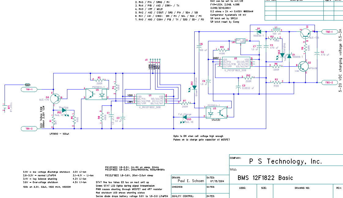
I have built part of the following BMS circuit and it seems like it works pretty well, although there are some issues:

Image


I have programmed the BMS PIC so that it starts to apply a PWM signal to the shunt resistor at 3.4V and turns on the shunt fully at 3.6V. I have the terminals for the battery connected to a current-limited power supply and as I increase the voltage to the 3.4V threshold, the PWM shunting drops the voltage so that the next time the samples are taken, it is below threshold, and so it toggles back and forth with what seems to be an excess amount of ripple. It is even worse when I adjust the current with a fixed voltage.

I think it will work better if I apply the current to the second set of terminals, and I can add the inductor and capacitors to smooth out the current applied to the cell.

The second portion of the circuit, not yet built, is a buck current converter that will use the comparator and the SR latch of the PIC12F1822 to provide a smooth regulated current from a voltage source such as a wall-wart or laptop power supply. It can be modulated by means of the second opto-isolator. This is meant to be a single-cell charging and discharge module to characterize a lithium cell and perform either top or bottom balancing. I can add a Bluetooth module to do datalogging.

One feature of this circuit is the isolated shunt circuit, which consists of just a 4.7 ohm resistor (I'm using 3.6 ohms in the prototype), an MJE170 BJT, and an opto-isolator. There is also a white LED with a 332 ohm resistor to indicate shunting. Total parts cost is well under $1, and it allows the shunting to be controlled for multiple cells in series, from a single PIC.

For voltage monitoring, I want to try using a DG408A (or DG508A) 8 to 1 multiplexer, which will be able to monitor the voltage of up to 8 cells in series (up to 28V or 36V for Li-Ion). It should present only a few microamps drain on unselected cells, and the sample for the selected cell can be read into a 100k/10k divider (or higher) that will have a maximum current draw of 28/100 = 280 uA for only a few mSec to take the reading. Thus the effective current draw for 1 second samples will be only a few uA. My immediate need is for a 6-cell BMS for an electric drill, but the same circuit could be used for an EV battery pack in clusters of 8 cells.
 
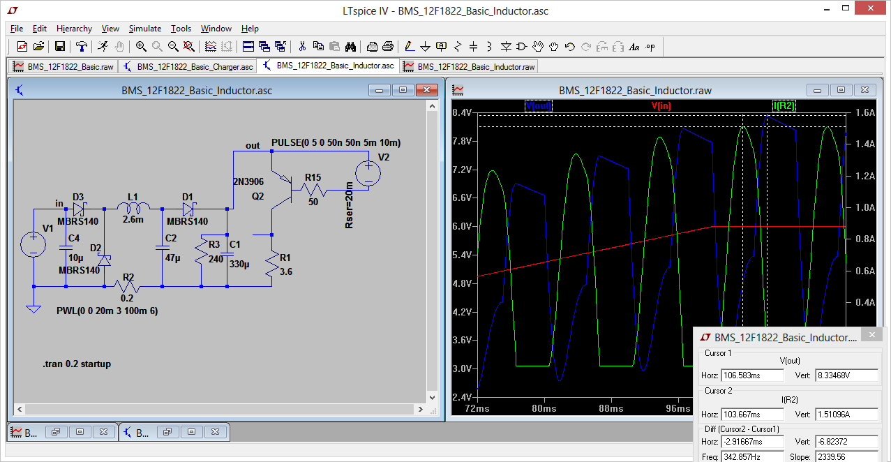
Well, the charging portion of that circuit may be problematic, especially without the second PIC, and using the inductor.

Image


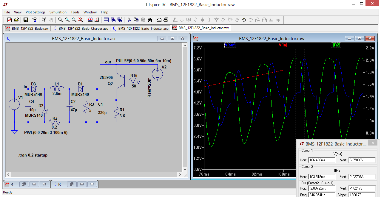
It's better with a 5 ohm load, but there is still a rather large voltage overshoot, which would be a problem for the 5V PIC to be used as a BMS element:

Image

http://enginuitysystems.com/pix/BMS_12F1822_Basic_Inductor.asc

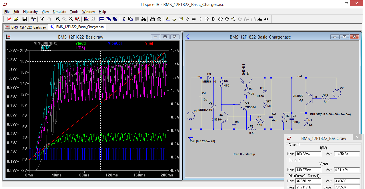
So, I made a linear current regulator using only discrete components, and the results seem much better. This is really more of a simple one-cell charger, with the BMS controlled by a PIC, and for a multiple-cell BMS a separate higher voltage charger would be used.

Image

http://enginuitysystems.com/pix/BMS_12F1822_Basic_Charger.asc

The charge current is basically determined by the voltage drop on the 0.5 ohm resistor R2 and the Vbe of the transistor Q4, which turns off the series pass element comprised of Q1 and Q3. I also added a 4.7V zener D1, which limits the output voltage to about 5.4V, protecting the PIC that will replace the pulse voltage source for the shunting resistor. There are also some components that are not really needed, such as D2, D3, and C2. I found C3 to be necessary to avoid oscillation, and its value may need to be adjusted in a real circuit.

It may even be better to use analog components such as precision voltage references and op-amps to provide the basic BMS and charging functions, at least for a simple single-cell charger. But I want to be able to use a PIC because of additional features, such as data monitoring, display, and logging.
 
charging adds a fair bit of complications no matter how you slice it, and active balancing isn't of much use if it cannot work while you drive, i.e. if you have a cell that is %10 below capacity of the others, the bms needs to be able to move %10/N charge to that battery, perhaps at hiway speeds, before the pack runs out, to make the most of your pack.

All that is really needed from a bms is a "service battery pack light" when it determines it is out of balance (plus charge/discharge voltage limits monitored per cell), plus temperature probes are good. A shunt is a nice to have, but I wonder how often they are really necessary (not thinking of the shunt top balancers here, though shunt usage there would be an indication of charge consistency). But having to balance at every charge seems like something is wrong with the system.

Edit: one useful thing a bms can do is keep track of which cell terminates charging, and if a different cell ever terminates discharge (or gets close enough for a warning) then consider that an out of balance condition. Otherwise the pack should be limited by the weakest cell, that's normal.

Also, I see the logic in bottom balancing, charging is done under fairly controlled conditions. Discharge can be all over the place, and if a cell goes low, the rest of the pack will turn on it. It isn't as convenient, but if the bms is integrated with the charger it can be automated. Top balancing isn't nearly as pragmatic.
 
Perhaps we need to revisit the purposes of a BMS and what it should or can do to protect the individual cells of a battery pack.

1. Overcharging can be prevented to a large degree by having charge current shunts that bypass any cell when its terminal voltage exceeds a safe level. But this is limited by the charge current that might be applied, and the power that can be dissipated in the shunt. A 1C charge for a 100 A-h pack will need to dissipate 36 watts just to shunt 10% of the charge. So there must be a way for the BMS to shut down the charger. If the charge is due to regeneration in a vehicle, there may need to be an external braking resistor, although this would only be a problem for a fully charged pack.

2. Depletion of a cell while drawing current can cause reverse polarity and irreparable damage, so it is necessary to detect this while operating the vehicle. Early warning of a cell nearing depletion can use throttle limiting to protect it while allowing limited "limp home" capability, but if the cell has become defective and has greatly reduced capacity, there may need to be another way to deal with it. An SPDT relay on the cell could bypass it and allow the vehicle to continue running at slightly reduced voltage, but this would require a relay (or semiconductor device) rated at over 100A.

3. Monitoring a battery pack during long-term storage may be useful to prevent excessive self-discharge, but the very act of monitoring presents a load that may easily exceed the self-discharge. However, there may be techniques that limit the monitoring current such that it will take several years to deplete the pack by 50%.

4. Cell failures (or connection failures) that create an open circuit cause a high voltage condition on the BMS that may be unavoidably destructive. It is possible to use a transient voltage suppressor (TVS) and a fuse that will disconnect the BMS in this case, but it requires a fuse rated for the maximum pack voltage, and a characteristic that opens quickly enough to avoid destruction of the TVS. This adds cost (probably at least $5/element), and the resistance of the fuse can affect the cell voltage measurement.

5. Overcurrent protection would involve a fuse, circuit breaker, or current sensor in series with the cell that would interrupt the excess current. Individual fuses and circuit breakers would need such high current and voltage ratings as to be impractical. Current sensors for each cell would add a lot of expense and/or voltage drop, but could signal the controller or charger to shut down. However, an overcurrent condition would probably cause a significant change in cell voltage, and this could be detected and transmitted to the controller.

6. Charge balancing can be accomplished by means of the shunt resistors. Top balancing occurs during charging as each cell reaches the shunting voltage threshold. Bottom balancing can be done by commanding the modules to activate the shunt resistor until the low voltage limit of each cell is reached. Because of practical limitations of shunt wattage, perhaps 5-10 watts, discharge would be in the order of 1 or 2 amps, so it would only be practical for a nearly depleted pack. It's possible to use a DC-DC converter to transfer the energy elsewhere, such as a pack that is being charged, but that adds a great deal of complexity and cost.

There may be other factors, such as temperature, that should be monitored. It's not very difficult or expensive, but would involve having a thermistor or other sensor attached to each cell with at least one wire connected to the BMS. It may be useful to monitor the overall pack temperature and/or the environment, to adjust cell voltage thresholds and charging or discharge current limits, and that is easily done by the controller or master BMS module. Extreme temperature rise in a cell due to failure could be monitored with a string of NC thermostats in series, and any one would shut down the charger or controller and sound an alarm.
 
for some of you vets this may seem obvious, but with the divider network approach it is possible to eliminate/minimize bms induced imbalance with a position specific resistor.

Here is a 6 cell node network, I am still tweaking it to be able to use 6 differential 1.1v referenced inputs on an attiny for a stack of 4.2v cells, and of course calibration is always needed, but you get the idea. With all the voltages the same at 4.1v the draw is identical @410uA, which is reasonably low. lower voltage cells draw less, so it is a tiny bit self-balancing. Good old thevenin :)
 

Attachments

61 - 80 of 138 Posts