DIY Electric Car Forums banner

Electric chopper trike build journal

3 reading
15K views 49 replies 5 participants last post by  electro wrks  
#1 ·
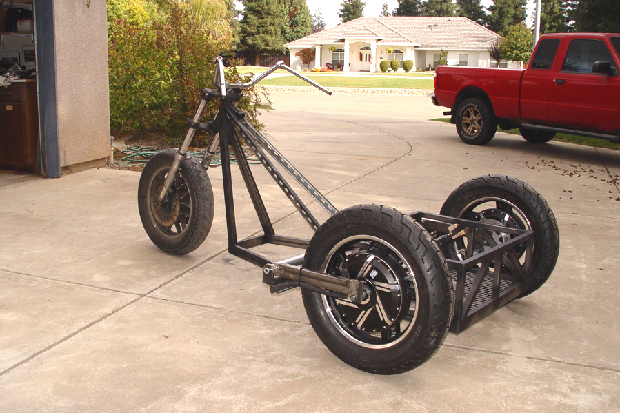
My goal for this project is to build a commuter vehicle capable of highway speeds (60 mph), a reasonable range (25 miles) and a budget that won’t require a second mortgage ($5K).

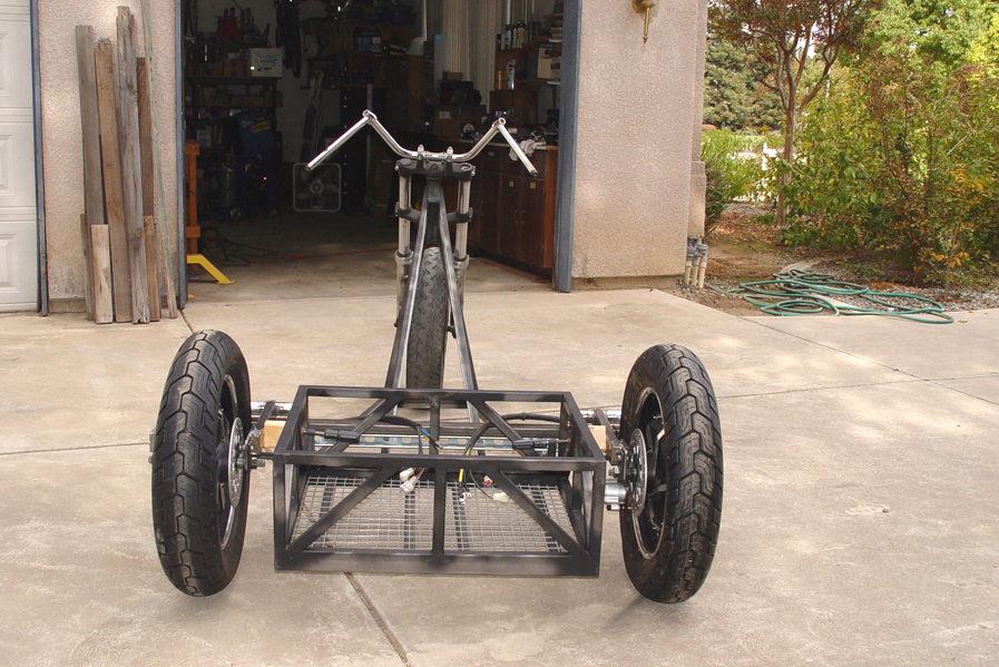
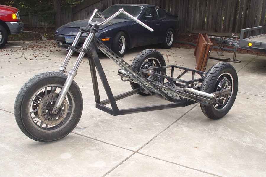
I have chosen to use a three wheeled trike design for the following reasons:
a) I am familiar with it from prior builds.
b) It is relatively light weight.
c) It is more stable (for me at age 72) than a two wheel “motorcycle”.
d) It is easier to license here in CA as a motorcycle than if it were a hand-built four wheel vehicle which would require licensing as a car.
e) although the trike will be “open air” I am fortunate to live in California’s Central Valley where year-round motorcycle riding is quite common.


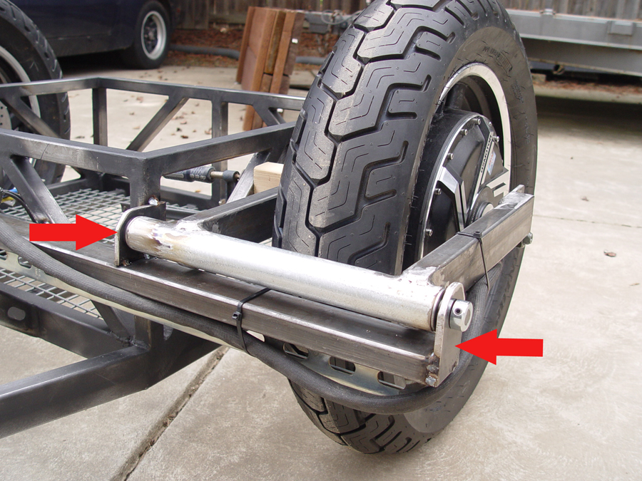
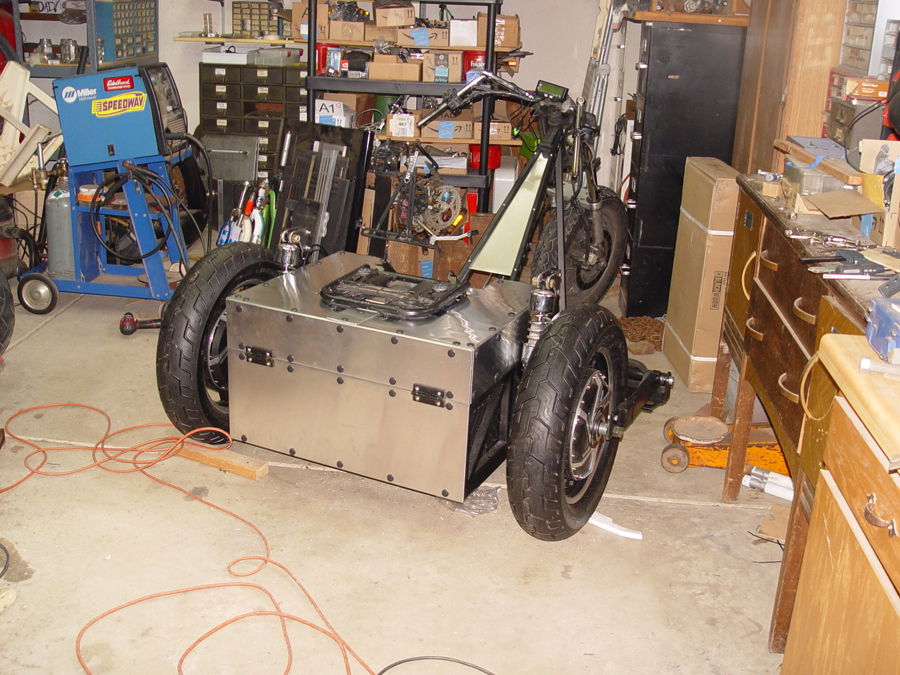
The trike will be built using two 3000W, QS Motors hub wheels mounted on the rear. The hubs have 16" rims, 273 ring size, 40H magnet size and are dual shaft, requiring drop outs on each side of each wheel. The other major electronic components include:
*Two Kelly controllers model KLS7230S (includes regeneration, electronic reverse, and cruise control)
*Two controller heat sinks
*Cycle Analyst V3 instrument cluster
*Dunlop Motorcycle tires (150/80/16)
*Kelly 400A72V contactor
*Holdwell ED250B-1 emergency shut off
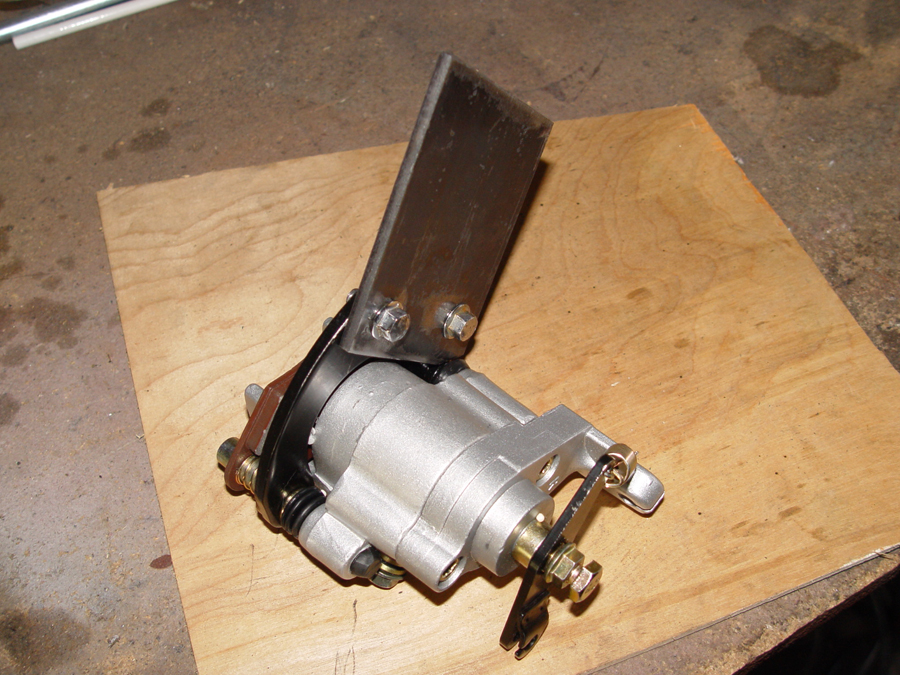
*Hydraulic disc brakes on both rear wheels
*Dual disc hydraulic brakes on front wheel
*Mechanical parking/emergency brake kit
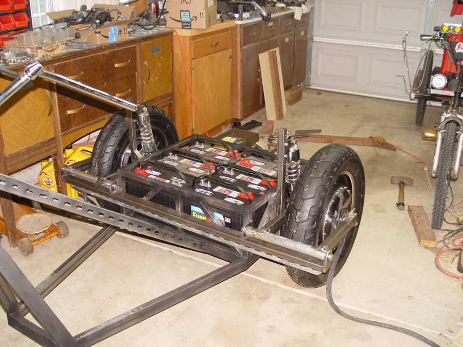
*6 - 12 volt EverStart 29DC deep cycle lead acid battery pack rated at 125 amphour.
*4 awg welding cable for all main battery wiring.


I will be posting my progress to this thread as well as a somewhat more detailed version on my own site,https://hotrodjalopy.com/ . Once on the site just click on the Electric Chopper Trike button to navigate to that build. You can follow the build and ask questions or make comments from either place.
 
#3 · (Edited)
Donor Bike

I will be custom fabricating the frame for the trike but many of the basic parts and pieces will come from a donor bike. For this purpose I purchased a 1989 Kawasaki Voyager 1200 which fit my needs and my budget ($500).


Image


The bike was in good running condition and had a clear title and the registration was up to date. So I will be able to use this title as the basis for legally registering the vehicle after the modifications are completed. (See Photo 1) Note: Please click on any photo for an enlarged version.
The parts I intend to use from the Voyager include:
*Front fork assembly
*Front wheel and tire
*Steering head
*Front dual disc brake assembly including hand controls and hydraulic system
*Seats
*Luggage carrier including adjustable (sliding) base and rack
*Progressive coil over shocks (Series 412 Model 4221)
*Headlight switch and dimmer
*Turn signal switch
*Rear brake pedal assembly
*Horn(s) and horn button
*Rear brake light, turn signal and running lights
*12 volt charger (for my separate 12 lighting system)
*I also intend to use the 97 HP Voyager engine and transmission in a shifter cart project which is next in line after this trike is completed.

The first step of the build process is to totally strip the Kawasaki down and set aside parts and pieces to be used for the trike build.


Image


The main component I am after on the donor is the front fork/wheel/dual disc brakes assembly. On the Voyager the front fork is welded directly to the frame and must be cut away. I left the "junction box" welded to the steering head so that I have something to weld the frame too.

Image


Image

 
#4 · (Edited)
Fabricating the Base Frame

The pieces for the base frame are cut from 1x2x.090 wall rectangular steel tubing.


Image


The frame pieces are squared up for welding. The red arrows note where the side rails were pie cut and bent inward.

Image


The base frame welded up.

Image

 
#5 · (Edited)
Mounting the Front Fork

The front fork will be set at a 28 degree angle (matching the angle of the original voyager) and held in place using two upright supports and two angled supports. While being set up for welding, the fork is held in position on an adjustable tripod (the orange legs in the first photo) to keep it at the correct rake angle. Note the lengths of 1x2 tubing (red arrows) which have been clamped to the side rails of the base frame, squared, and extended forward. These rail extensions act as guides for centering the front wheel and fork with the frame base.

Image


The steering tube and front fork have machined “stops” (red arrows in the photo below) and a centering pin (white arrow) which prevent the front wheel and fork from being turned too far left or right thereby creating a dangerous or unstable condition. By fitting identically sized wooden shims between the center pin and the stops on each side, the fork and the “junction box” can be clamped in place at dead center to insure the junction box, steering head and front wheel will be pointed straight forward when the fork is welded to the frame.


Image


Image


The two front uprights and the two angle supports to the frame are then welded in place to permanently mount the front fork.


Image

 
#6 · (Edited)
Battery and Electronics Box

The batteries and electronic components will be located between the rear wheels and behind the seat. The box will be 24″ x 29″ x11″ (external dimensions) to accommodate the six lead acid batteries. 1x1x.0625 square tubing is cut for the perimeter of the battery box.

Image


The tubing is squared up and welded to the frame base to form the box.

Image


Additional 1×1 tubing is cut and welded to form the box’s angle bracing. This bracing provides support and strength to the box and to the frame itself.

Image

 
#7 · (Edited)
Swing Arm Fabrication

The rear wheels will be mounted to the frame using U-shaped swing arms which support both ends of the wheel’s axle shaft. Fabrication of the arms begins by making drop out brackets for the axles. The drop out plates are cut from 1/4 inch steel plate. Two holes are drilled in each plate. The larger whole is drilled to match the axle diameter. The smaller whole is for mounting an axle torque plate. The holes are drilled using a jig on the drill press to insure all four drop out plates match up. The torque plate is also made from 1/4 inch flat stock and is designed to prevent the torque of the hub motor from twisting or spinning the axle within the slot of the drop out. The QS hub wheels come from the factory with prefabricated torque plates which have a very precise fit on the axle shaft. The axle holes in the drop out plates are cut open to allow the axle to slip out the bottom.

Image


The side arms for the swing arms are cut from 1x2x.090 rectangular tubing. The tubing is first cut to TWICE the length for each arm. My arms are going to be 13 3/4″ long but this will vary depending on wheel/tire size and other design differences. Draw a line exactly half the length of the tubing and then drill a hole 1 ½” in diameter in the center of the arm. I used a metal cutting hole saw in the drill press to do this.

Image


Cut the 1×2 tubing exactly in half based on the center line which was drawn earlier. This cut will also be directly in the center of the 1 1/2″ hole.

Image


You now have two arms notched to fit quite nicely around 1 ½” O.D. tubing and ready for welding. The pivot tube for the swing arm is cut from 1 1/2″ O.D. tubing. The length of the pivot tube will vary depending on wheel width and mounting position considerations but for this project the tubes are 13 3/8″ long.

Image


The drop out plates are tack welded to the side arms and then the side arms with drop outs are bolted to each side of the wheel axle. The pivot tube is lined up in the side arms, clamped in place and tack welded.

Image


The completed left swing arm.

Image

 
#8 · (Edited)
If that's thin wall electrical conduit you're using for the swing arm pivot tube, it might not be strong enough for this application. I would use the stock swing arm tube's wall thickness as a guide for what would be required. You probably have pivot bearings lined-up that fit nicely in the conduit. But, be prepared to have to reinforce the conduit tube or switch to a heavier wall tube.

I've actually used thin wall conduit tubing on a swing arm before. But, it was on a bicycle trailer 1/10th weight of your trike.
 
#9 · (Edited)
Brake Caliper Mounting

Although I take no credit for planning it out this well, the brake caliper can be mounted in the correct position on the disk by simply dropping a piece of 1/4" flat stock directly down from the swing arm drop out plate and then bolting the caliper onto the plate. I made a pattern on card stock paper to get the bolt holes right and then drilled the plate for the mounting bolts.

Image


Here's a shot of the simple plate/bracket bolted to the caliper. Not so pretty, but functional.

Image


The wheel and swing arm are positioned on the trike's frame and clamped tightly in place. The caliper and bracket are fitted in place with the brake pads slipped over the rotor to insure everything lines up correctly and that the caliper does not interfere with any frame components. The bracket (see arrow in Photo 3) is clamped to the swing arm and then tack welded in place. The caliper is unbolted and removed and then the bracket and swing arm are removed from the wheel and trike as one piece for final welding.

Image

 
#10 ·
Mounting the Swing Arms

A swing arm mounting bar which spans from wheel to wheel is cut from 1x2x.090 rectangular tubing and clamped to the existing frame of the battery box with the 2″ dimension in the horizontal position. (See upper arrow in Photo). A second bar is cut from perforated channel strut and is welded with the long dimension in the vertical position to the underside of the 1×2 tubing (see lower arrow in Photo). This prevents the mounting bar from flexing either vertically or horizontally.

Image


Brackets for attaching the swing arm pivot tubes to the mounting bars are cut from 1/4″ flat stock and drilled with ½” holes. There is a size and shape difference between the inside brackets and outside brackets but all four bracket holes must line up in the same position. So as each plate drilled it is marked for proper positioning. The exposed corners of the bracket are trimmed off and ground to a smoother shape.

Image


Half inch steel rod is cut to length to fit the pivot tube length plus bearings plus brackets plus end collars.

Image


Flanged bearings with ½” I.D. and 1 3/8″ O.D. are fitted into each end of the pivot tube (see arrow in Photo). These particular bearings are rated for a dynamic load of 4900 lbs.

Image


With the swing arm, wheel/tire, and pivot tube square to the frame, the pivot tube brackets (arrows in first Photo below) are clamped and tack welded to the horizontal mounting bar. Once it is certain everything is square and true, the brackets will be permanently welded to the mounting bar. The passenger side swing arm is then welding in place in the same way. The 1/2″ rod is capped on each end with a 1/2″ I.D. collar and set screws. (last Photo)

Image


Image
 
#11 ·
It's a Roller

This is a fun day in the progress of any project. The day you can roll the beast out of the garage on its own two, three or four wheels. The chopper trike has no rear suspension yet but with the swing arms clamped in position the bike sees daylight. These photos also begin to hint at how the trike will look in a more finished state.

Image


Image


Image


Image


Image
 
#12 ·
Rear Suspension

Positioning the rear spring/shock mounts and setting them at the right height can be a daunting task on any scratch built project. During the fabrication process there is no weight on the frame and the mounting points for the top and bottom of the spring/shock are just theoretical points in space. Once the vehicle is completed and under full weight, including the rider, the suspension is going to compress and the vehicle is going to end up at a different ride height than during construction.

The Kawasaki donor had a nice pair of aftermarket Progressive 412 Series, adjustable coil over shocks on the rear which will be used on the new trike. Calculating final ride height and shock compression can be even more of a challenge when using progressive coil springs such as these. With a progressive spring, the spring rate increases as the coil is compressed. My 412-4221 coils, for example, have a spring rate of 140 lbs per inch when fully extended. But they have a spring rate of 200 lbs per inch when fully compressed. And that rate is constantly changing and getting greater over the full 3.52 inches of spring travel. Theoretically the spring rate increases with every incremental increase in compression distance. In actual practice, however, the increase is not perfectly linear. But for estimating ride height one can assume a linear rate increase and get things relatively close.

For this trike I wanted the springs and shocks to be compressed approximately ½ way when the trike is completed and sitting at ride height with the rider aboard. So I calculated an average spring rate over the first half of the spring’s compression (155 lbs per inch for my shocks). I then estimated the total weight of the finished bike and rider AND the estimated weight distribution front and rear. In my case the battery pack will weigh 360 lbs and I estimated 85% of that over the rear wheels and 15% over the front. The rider weight will be 170 lbs distributed 50/50. The frame, seats and all other components were estimated at 150 lbs also distributed 50/50. These calculations put the total weight over the rear wheels at 466 lbs. That weight will be distributed 50/50 between the rear wheels so each spring/shock will support 233 lbs. Dividing that number by the spring rate of 155 lbs per inch indicated each spring would compress approximately 1.5″ with the bike finished and the rider aboard. I wanted the finished bike to sit level at 6″ above the pavement with the rider aboard so I set the frame on 6″ blocks at the front and 7.5″ blocks at the rear. The swing arms, however, are positioned absolutely horizontal to the pavement. With the spring/shock fully extended and the lower shock eye bolted to the swing arm, the position of the upper spring eye can then be identified relative to the frame and future shock mount.

Since my knowledge of spring physics is quite limited and my mathematical and theoretical calculations always suspect, I allowed myself a fudge factor during fabrication by making my shock towers adjustable. I cut the 1×1 tubing for the towers about 2″ longer than my calculation and then I drilled a series of 11 holes, at half inch intervals, in the tower. (Photo below) This will allow for adjustment of the upper spring brackets either up or down should the spring position calculations be in error. Once the trike is complete any excess holes at the top of the tower can be cut off and removed.

Image


The upper shock mounts are created by making 3″ x 4″ plates cut from 1/4″ flat stock. Using a simple jig in the drill press, the four shock mounting plates are drilled out.

Image


The large single hole in the plate is for the shock eye bolt and the two smaller holes are for bolting the plates to the shock tower. Each plate must also be notched on the bottom to clear the top of the coil/over shock. A total of four matching plates must be made, two for each shock tower.

Image


The plates are bolted to the spring tower at the estimated height indicated by the spring rate calculations. Note the extra mounting holes for adjusting the ride height.

Image


The lower spring mount is much easier. It is a 5/8″ grade 8 bolt inserted through the swing arm and drop out plate.

Image


To align the top mounting plates with the lower mounting bolt, a spacer cut from 1″ x1 1/2″ rectangular tubing is welded to the shock tower. (See red arrow Photo below)

Image


The spacer and shock tower will be welded to the frame base and battery box in a vertical position. The tower, however, will be positioned so the upper shock mounting hole on the tower will be a little forward of the lower shock mounting hole on the swing arm. This creates a forward shock angle of approximately 10 degrees. Putting the spring/shock at an angle reduces the effective spring rate. I used an angle similar to what was on the donor Kawasaki. If the ride is too harsh or to spongy once the bike is completed, the Progressive 412 shocks can be adjusted to compensate for the miscalculation. With the swing arm parallel to the ground and the lower spring eye attached to the lower mounting bolt, the shock tower with mounting brackets attached can be positioned on the frame so that the upper spring eye, with the shock fully extended, fits exactly between the holes of the shock tower brackets. If things are “off”, the shock tower brackets can be moved to a higher or lower hole in the tower until everything lines up. When completed the shock tower should be in a vertical position with the bottom of the tower even with the bottom rail of the battery box. The photo below shows the shock tower welded in place after the position had been established with the swing arm and spring/shock in place.

Image


With the shock towers welded in place the swing arms are once again installed and the coil over shocks can be bolted in position.

Image


To see if our calculations, estimates and guesswork for positioning the springs is anywhere near correct the batteries are loaded into the battery box . At this point the trike is still about 3/4″ above my design ride height. Once the rest of the framework, electronics, seat, and driver are added, the trike should be within 1/4″ of where I want it to sit. So I may have lucked out with my original calculations and hopefully I won’t have to make any major alterations.

Image


With the upper shock mount position now established and reasonably tested for accuracy, an angle brace is cut and welded to each shock tower to triangulate with the frame and stabilize the towers.

Image
 
#13 ·
Mounting the Controllers and Heat Sinks

It may seems a bit early in the trike’s progress to by mounting electrical components, but the controllers not only pose a size factor, they must also be positioned so that all the wire harnesses will reach, they can be properly protected from the elements and they will not interfere with any of the other main components of the trike yet to be fabricated. The controllers will be positioned just above the battery box and will be covered by the deck lid which will be constructed later.

Two support bars are cut from 1x2x.090 rectangular tubing and they are bolted in the battery box so that they are removable (see arrows in Photo below) The bars serve a dual purpose. First, they lock in the batteries so they can not come loose in the event of an accident. And second, they provide mounting support for the controllers/heat sinks as well as other electrical components which will be located under the rear deck lid.

Image


Brackets to mount the heat sinks to the bars are cut from 1 1/4″ angle iron.

Image


The brackets are bolted to the pre drilled holes in the heat sink.

Image


The heat sink with brackets bolted on is then positioned and clamped in place so that the mounting brackets can be tack welded to the outer perimeter of the battery box and to the inner support bar. (See arrows in Photo below showing the heat sink brackets welded in place)

Image


The heat sinks are temporarily bolted in place.

Image


And the controllers are bolted to the heat sinks.

Image
 
#14 ·
Rear Deck Lid

Now that the position and height of the controllers and heat sinks have been established, a rear deck lid/battery box cover can be constructed using 1x1x.065 square tubing. Note that there is an indentation in the front portion of the deck lid. This space is needed so that the seat back will be able to recline into the deck lid.

Image


The deck lid is then test fit on the battery box. Note that the controllers are still bolted in place to insure there is proper clearance with the deck lid. Also note the indentation in the front of the lid where the seat back will recline.

Image


And a view of the deck lid from the rear being checked for proper fit.

Image


The lid is hinged using common steel door hinges. However, the hinges must be cut down and then re-drilled so that the mounting bolt holes will line up properly with the 1×1 tubing of the battery box and deck lid. An original hinge is shown on the right and the cut down version on the left.

Image


To mount the hinges flat on the surface of the battery box and have them operate properly, spacers are cut from ½ x 1/16″ flat stock and welded to the back side of the steel hinge.

Image


Bolt holes are drilled through the hinges and tubing and the hinges are secured to the battery box and deck lid. (See arrows in Photo below).

Image


With the hinges in place the rear deck lid can be swung to the open position.

Image
 
#15 ·
Mounting the Cargo Case

The cargo case from the donor Kawasaki will be mounted on the deck lid and will also serve as a portion of the seat’s back rest. The Kawasaki was equipped with an adjustable sliding base which will be used on the new trike to provide some flexibility in the positioning of the cargo case and allow for a bit of fudge factor when the rest of the seat is constructed later. The slider base is a little too long to fit in the deck lid so the front legs will be cut off approximately at the red arrows.

Image


Rear mounting brackets for attaching the case to the base are made by welding flat stock to angle iron.

Image


The front of the base frame will bolt directly to a cross member in the deck lid and will not need mounting brackets. Photo below shows the underside of the installed slider frame. The rear mounting brackets are indicated by the red arrows and front mounting bolts are indicated by the white arrows. In this photo you can also see the slider release mechanism which allows the case to be moved forward or backward.

Image


The installed slider frame from the top.

Image


The cargo case can now be bolted to the slider frame.

Image


The deck lid now swings open with the cargo case attached.

Image
 
#16 ·
Seat Back

I am using the passenger seat from the Kawasaki donor as a seat back/back rest on the new trike. The underside of the seat back is formed plastic with four threaded bolt receivers fused into the plastic. These will be used for attaching to an adjustable bracket which will then be mounted to the frame of the trike.

Image


Four mounting tabs are cut from angle iron and drilled for bolts and two mounting rails are also cut from angle iron and drilled for bolts.

Image


An adjuster arm is cut from 1/4″ flat stock and drilled with a series of adjustment holes. This will allow the angle of the seat back to be altered for the most comfortable riding position.

Image


The tabs, rails and adjustment arms are bolted to the bottom of the seat back. The bottom of the seat back rail (on the right in Photo below) will remain in a fixed location but can be pivoted around its attachment bolt. By selecting different mounting holes the top of the rail (on the left in Photo) can be adjusted either forward or backward to provide optimal back support and a comfortable riding angle.

Image


Image


The mounting assembly is taken apart and the two side rails (see red arrows in Photo below) are positioned and welded to the frame of the rear deck lid.

Image


The mounting hardware can then be reassembled and the seat back bolted in place and adjusted to the desired angle.

Image


The cargo case now opens normally from the rear while the deck lid, cargo case, and seat back can be swung up and open for access to the battery pack and electronics.

Image


Image
 
#18 ·
... I've been enjoying your build log and I learned a bunch of things.
Thanks MattsAwesomeStuff. I think the primary function of a build journal ISN'T that folks will want to run out and build an exact duplicate, but rather they will discover a little trick here or a little technique there that they can incorporate into their own personal creation. Some folks may not like the final product at all, but hopefully in the details they can find some useful tidbits. So I share your enthusiasm for detailed journals with lots of photos.
 
#19 ·
Mounting the Seat

The seat is taken directly from the Kawasaki donor bike. Like the seat back, the seat itself also has a formed plastic base. But unlike the seat back it does not have terrific mounting points. The front of the seat originally mounted via a pair of “C” shaped plastic tabs shown with the white arrows in the Photo below. The rear of the seat was held in place with a pair of plastic mounting tabs shown with the red arrows. Unfortunately the rear mounting tabs are not very strong and are meant only to keep the seat from moving around and not meant to be load bearing. Instead, all of the weight on the seat was originally transferred to the formed plastic which rested directly on the frame of the Kawasaki. As a result, the two plastic attachment tabs at the rear of the seat can not bear much weight.

Image


Fortunately, there is a strong, flat area molded into the back edge of the seat (see red arrow in Photo below). This area is strong enough to support the back end of the seat while the front of the seat will rest on the frame of the trike itself. The front “C” clips will still be used to keep the front of the seat held in place but will not be load bearing.

Image


A support bracket at the rear of the seat is made using a length of angle iron which is bolted to the two plastic mounting tabs. Quarter inch flat stock is then used to make a mounting pad which rests on the solid flat portion of the formed plastic. The flat stock is positioned and welded to the angle iron cross piece.

Image


This is what the rear mount and seat support looks like when it is welded together and removed from the seat.

Image


With the rear bracket back on the seat, two support posts are cut from 3/4 x 3/4 rectangular tubing and bolted to the support bracket.

Image


The seat is then flipped over and the support posts are bolted to small tabs welded to the frame of the trike. Additional holes can be drilled in the support post to raise or lower the rear of the seat to get a more comfortable angle if necessary.

Image


The front of the seat is held in place using a ½” steel rod which passes through the trike frame (enclosed in a steel tube) and the two “C” clips on either side of the seat. The inside of the plastic “C” clip fits snugly against the trike frame preventing the seat from moving left of right and the clip and steel rod prevent the seat from moving upwards. The rod and “C” clip act as a hinge so that the angle of the seat can be adjusted by moving the rear seat bracket up or down.

Image


While the seat can not move forward because of the steel rod and “C” clip, it could possible collapse toward the rear of the trike if the bolts on the support posts were to loosen slightly. To prevent any rearward movement of the seat, brackets are welded to the rear seat support and the center of the trike frame and an adjustable turnbuckle is bolted to the brackets.

Image


The completed seat with adjustable back rest.

Image
 
#20 ·
Brake Pedal Assembly

The rear brake pedal assembly from the Kawasaki Voyager donor will be used on the new trike.

Image


Image


Quarter inch flat stock is used to create a mounting plate for the brake pedal assembly.

Image


The mounting plate bolted to the brake pedal assembly.

Image


Since the lower frame rail of the trike runs at an angle, the brake pedal bracket must be offset so that the brake pedal arm will clear the frame. A wedge shaped spacer is cut from 1/4″ flat stock to set the brake pedal assembly at the correct angle.

Image


The wedge shaped spacer is welded to the mounting plate. (See red arrow in Photo below)

Image


The entire brake pedal assembly and mounting plate are positioned on the frame to place the pedal where you want it and the assembly is clamped in place for welding.

Image


The final mounting position of the mounting plate is too close to the frame to remove the attachment bolts. So the bolts are permanently welded to the mounting plate. The Photo below shows the completed mounting plate welded to the frame with the pedal assembly removed.

Image


The completed brake pedal assembly bolted to the frame.

Image
 
#21 ·
Parking Brakes - Part 1


The electric trike will require an emergency brake/parking brake primarily to keep the vehicle from rolling when it is parked and shut off. Unlike a car or motorcycle with a mechanical transmission which can keep the vehicle from rolling when it is parked, the electric trike will roll fairly easily if it is on even a minor grade.

The hydraulic brake system I purchased from QS Motors comes with calipers which have a built in emergency and parking brake mechanism and the system also includes the cables and attachment hardware for operating the system. The kit does not, however, include the parking brake handle or a ratcheting mechanism. In addition a bracket must be fabricated for securing the brake cables to the trike’s frame.

The cable mounting bracket is cut from 1 ½” x 1 ½” angle stock. A hole is drilled to fit the threaded fitting at the end of the brake cable.

Image


The holes in the bracket are opened up to the outer edge so that the brake cables can easily be installed or removed from the bracket.

Image


A cross piece is cut from 3/16″ flat stock so that it can fit the width of the frame. The cable mounting bracket is welded to the cross piece.

Image


The cross piece is bolted to the frame and the cables are secured in the mounting bracket.

Image


Photo below shows the underside of the cables bolted into the mounting bracket.

Image


The brake handle and ratcheting mechanism are an aftermarket unit made to fit a Volkswagon Beetle. These brake handles are primarily used in baja bug type builds and can be purchased for $25-$30.

Image


A mounting bracket for the brake handle is cut from 3/16″ flat stock and drilled for the mounting bolt. The holes on each end of the bracket are for bolting it to the trike’s frame.

Image


Photo below shows the brake handle bolted to the mounting bar.

Image


The only drawback to using the Baja bug brake handle is that the ratcheting mechanism is not held stationary by the handle itself. Instead, the slot shown at the red arrow in the Photo below normally hooks to a tab on the Volkswagon driveshaft tunnel and this tab holds the ratcheting mechanism in a fixed position. So a stop must be fabricated to keep the ratchet fixed.

Image


The stop is cut from angle iron so that it fits the slot but will not interfere with brake lever as it is engaged or released. [Note: this section continued in following post.]

Image
 
#22 ·
Emergency Brakes - Part 2

The stop is positioned and then welded to the brake lever mounting bar.

Image


Photo below shows the brake lever bolted to the mounting bar and the ratchet stop (red arrow)

Image


Photo below shows the entire brake lever mechanism and stop bolted onto the trike’s frame. The red arrow shows the ratchet stop.

Image


Photo below shows the brake lever in the released position. In this position it will be tucked under the “dash” of the trike and partially hidden from view once the dash is installed.

Image


The final Photo shows the brake lever in the engaged position. When engaged the level protrudes out from under the dash and will be easy to spot to remind the rider to release before engaging the motor.

Image
 
#23 ·
Variable Regeneration Controls - Part 1

My Kelly KLS7230S controllers are capable of providing variable regeneration. To alter the amount of regeneration the controllers need a 0-5 volt signal. The simplest way to provide that variable signal would be with a common twist or thumb throttle located on the handlebars. But I felt a second twist throttle, or even a thumb throttle would be confusing and sort of counter intuitive. I felt a better solution might be to mount a typical brake lever on left side handlebar and then run its cable to a thumb throttle mechanism located toward the rear of the trike. My thinking is that this will provide the more natural “feel” of a traditional motorcycle hand brake when the regen is activated.


Unfortunately, the “throw” of most brake levers is not quite long enough for the cable to pull the thumb throttle from the zero position to the full throttle position. As a result, the controllers would not receive a signal for maximum regeneration. To remedy this situation I needed a way to “gear up” the cable so the brake lever movement can provide a longer pull.


To do this I am using a freewheel body from an old six speed cassette stack. Note that the freewheel body has two grooves (arrows), one larger than the other. By running the incoming brake lever cable around the smaller diameter groove and the outgoing thumb throttle cable around the larger groove, the pull of the brake lever can be multiplied enough to move the thumb throttle lever from its zero position to its 5 volt (maximum) position. The six speed freewheel body is threaded onto the wheel hub allowing it to freely rotate while still being held in the proper position.


Image


Only the threaded “cassette” side of the wheel hub is needed, so the balance of the hub is cut off leaving the hub disk and threads as a mounting platform for the freewheel body.


Image


The hub disk is ground flat on the back side.


Image


To guide the cable from the brake lever onto the groove of the free wheel, an old brake lever handle is cut apart saving the guide (arrow) and a portion of the lever which is drilled for mounting bolts.


Image


With the freewheel body unscrewed and removed we can see the threaded mount of the hub disk. Two 1/4″ holes (arrows) are drilled in the hub disk for mounting.


Image


The components are laid out on 3/16 x 3″ wide flat stock. On the left is the “guide”, in the middle is the freewheel body “gear multiplier” and on the right is the thumb throttle. (Photo 6) When everything appears to be in alignment for smooth operation, the mounting points for each component are marked and the flat stock can be cut to the appropriate length and appropriate holes drilled for mounting the guide and the hub disk. The thumb throttle is mounted on a short length of handlebar tubing which is welded to the 3″ flat stock.


Image


The components attached to the base. The thumb pad of the throttle will have a small hole drilled through the center for inserting the cable.


Image


To secure the end of each cable in the freewheel body groove a “bridge” is welded over the top of each groove. The cable is then inserted into the groove and under the bridge. To insure the weld does not go all the way to the base of the groove, making it impossible to fit the cable under it, a large diameter copper wire is placed in the groove while the bridge is tacked in place. The copper will not bind to the weld and can be pulled out once the weld has cooled. The cable can then be threaded under the bridge, tightened and a stop crimped to the cable. [Note: Variable Regen continued in next post.]


Image
 
#24 ·
Variable Regeneration Controls - Part 2

Note that the cable from the brake lever to the freewheel body “gear” needs to be adjustable in order to get the cable tight. Instead of crimping on the stop, a cable ferrule is used and a small screw inserted into the open end of the ferrule and tightened securely.

Image


The thumb throttle has its own spring to return it to the zero position but to insure the throttle does not hang up due to friction in the cable or gear mechanism, an additional spring (arrow) is attached to the back side of the throttle lever.

Image


The variable regen mechanism is then bolted to the trike frame. With the cables attached the left hand brake lever now operates the thumb throttle which, in turn, engages the regeneration function of the two Kelly controllers on a variable basis. The harder you squeeze the brake lever, the greater the amount of regeneration AND the greater the amount of braking effect created by the regeneration.

Image
 
#25 ·
Unfortunately, the “throw” of most brake levers is not quite long enough [...] To remedy this situation I needed a way to “gear up” the cable [...] To do this I am using a freewheel body from an old six speed cassette stack.
I appreciate the resourcefulness.

I think just attaching the cable lower down on the regen lever would've been a lot easier. Taking it apart if you had to. Or, if not, a simple 1/8" piece of metal with a pin in the middle to pivot on would've sufficed. Short lever on the brake lever side, pivot in the middle, long lever on the regen side.

Levers are a lot simpler than freewheels.

But whatever, I like seeing a different way of solving a problem.
 
#26 ·
The lever set-up would probably have been simpler and I may go to it yet depending on how the freewheel thingy works over time in real life. I have also been told that Problem Solvers makes a little gizmo called the "Travel Agent" which one can buy to manipulate the throw distance of a cable. My personal preference is normally to just head for my junk bin to find something that might work to solve a problem. I call myself Mr. Thrifty...my wife calls me Mr. Cheap SOB.
 
#27 ·
Plywood Core Body Panels - Part 1

To protect the electrical components and wiring for the trike, body panels will be made to enclose the battery and electronics compartment. A body panel will also be created to serve as a “dashboard” for mounting switches and to enclose wiring at the front of the trike. The body panels will be made using lightweight and relatively inexpensive aluminum flashing. Used alone, flashing is too thin and would reveal bumps, bows and other distortions in the metal. So I am using a technique I have used to make dashboards and other panels for some of the hot rods I have built. Each panel has a “core” made from 1/8″ plywood. The aluminum flashing is then cut and glued to the core to form a solid, stable surface. Note that this technique can only be used on flat surfaces or surfaces curved in only one direction. It can not be used for compound curves or compound/complex curves.

Each panel section core is measured and then cut from 1/8″ plywood. Photo below shows all the plywood panel cores for the chopper trike.

Image


Aluminum flashing is cut to the outer shape of each panel with ½” to 5/8″ of extra material on all edges. Do not cut out irregular shapes of the panel at this point.

Image


Apply DAP Weldwood contact cement to the front of the plywood and the rear of the aluminum. Dry for the recommended time period and attach the aluminum panel to the plywood panel making sure to leave ½” of flashing extending beyond the plywood on all edges.

Image


From the plywood side, a simple panel will look something like the Photo below. Note that none of the irregular shapes have been cut out at this point.

Image


On the flashing side the panel will look like the Photo below.

Image


Using a good set of tin snips or metal cutting shears cut each outside corner as shown in Photo below.

Image


Inside corners are cut as shown in the Photo below. Once all corners have been cut, apply contact cement to the exposed surfaces and to the back side of the plywood, wait the appropriate time, and then fold the edges of the flashing over the edges of the plywood and press firmly in place on the back side of the plywood.

Image


The finished panel should look something like this.

Image
 
#28 ·
Plywood Core Body Panels - Part 2

This Photo shows all of the completed plywood core body panels for the chopper trike.

Image


The “dashboard” panel is installed with machine screws for easy removal.

Image


The other body panels are attached using nylon push type fender rivets. These rivets are most commonly found in automotive application for both interior and exterior fastening. The rivets can be removed once they are in place but they do sometimes break off or become difficult to remove. So if you know a body panel is going to be on and off a number of times it might be better to use a different type of fastener, such as a machine screw. Also, some may want to choose a different fastener if the do not like the “look” of the nylon rivets.

Image


Photo below is a close up of an installed fender rivet.

Image


The top panels of the battery box lid are riveted in place.

Image


Access holes for electrical wiring are cut in the body panels with a hole saw.

Image


Rubber grommets are used to enclose the holes and protect the wiring.

Image


The front view of the completed body panels. Note that the two openings at the upper left and upper right of the deck lid are purposely left uncovered to allow air flow to help cool the controllers and the battery box.

Image


The completed battery and electronics compartment from the rear.

Image