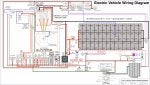
I have been working on a diagram for my S-10 pickup conversion over the past few days. I would like to know what is wrong or should be done differently. I have pieced this together from multiple sources and they don't always show you how one component is supposed to work with other ones.
And I was disappointed that I couldn't find something like this, as I think it would make buying the parts you need and knowing how they all go together easier.
I still have to add the gauges and lights, although the lights should already be wired up correctly with the switches in the dash. And the Raspberry Pi will be a Bluetooth adapter and CANbus string parser, but that will happen later. I still need to look into the power steering and power brake components.
Do you see any mistakes? I am questioning the fuse placement and size in a few spots. Am I missing something obvious?
Thanks
(Look at page 6 for the latest - Version 25, it is interesting to see how much has changed in 18 months. It is much easier to change things now than in the vehicle.)
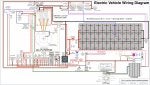
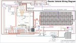
") . But everything works great eventually. I just have blown up some parts in the past. I am trying not to do that this time, and I appreciate all of the help.
. But everything works great eventually. I just have blown up some parts in the past. I am trying not to do that this time, and I appreciate all of the help.