DIY Electric Car Forums banner

Honda IMA

1 reading
77K views 109 replies 15 participants last post by  Stark  
#1 ·
Anyone looked into the Honda IMA drives?

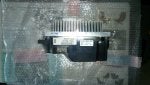
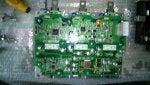
Both the inverter part and the motor section look good. The highvoltage drivers are separate from the brain box so might be easily adapted.

Also the highvoltage drivers are going for low bucks, 100-200 bucks usually for the complete set of dc-dc, compressor driver and motor inverter.

Anyone know of projects reusing honda parts?
 
#3 ·
yes I know, how ever the inverter side of things is very interesting.
Got some quite complete documentation of the operation and pin outs of various years.

The ima motor can be had very cheaply and the 20 kw peak is just rotation and cooling limited. It has quite a high torque output, so some custom engineering can result in quite a nice package.
 
#7 · (Edited)
Got my motor and power electronics in today. Motor is alil bigger than expected.

The power electronics look quite good the caps are rated at 600v 460uf and smaller snubbers included. So a ready to go package, now to get my pinning sorted and get try to test the outputs.

The power electronics has part number 1B100RMXE07
 

Attachments

#8 ·
Might have gotten myself in alil too deep with this one, One generation too high maybe.

Looks like this one got more intelligence than i would want, canbus communication. :( So i would need to get a hybrid to decipher the canbus.
 

Attachments

#9 · (Edited)
I had a look at the IMA drives and controllers, i thought their maximum voltage was 144 volts and the power output was 20kw? which is great for bike conversions or go carts but a little low for a car, what are you plannning on making with it?

love to see the pictures btw looks like some really nice hardware.

btw I was sure the older version of this just had six outputs for controlling each switching transistor and the outputs for the current sensors, i think you may be right to say you would be better with one of those.
 
#10 ·
do you see the pictures posted? These are of the parts i have now.

Digging through the insightcentral forums for info if some-one has cracked the IMA-canbus.

Planning on getting this "inverter" MCM or whatever you want to call it running, and then upping the voltage till it cuts out. As far as an vehicle I have not made a choice yet.
 
#16 ·
Tom,

I did pretty much the same as you. The motor/housing isn't too bad to deal with and the inverter shouldn't be too difficult using one of the Lebowski or Eldis solutions. When you remove the top board, you have direct access to the IGBT drivers and IGBT's. One trick is that the power to the drivers is on the top board, so you either need to keep the top board for power while disconnecting the PWM's, or provide external power. Lebowski's board might be easier to use without the top board, Eldis's, with.

The motor, again, is fairly easy to deal with. The rotor is easily adapted (no splines!) and he housing is pretty easily made. You could use the stock aluminum housing if you'd like, but it is pretty bulky and it would be more difficult to integrate liquid cooling.
 
#17 ·
You got any progress that you care to share with us? Any pictures of the module without the top board?

If i get tired to trying to reverse engineer the canbus, ill dive into the topboard to find where the driving signals are located.

This weak I am going to hook the resolver onto the inverter and see if i get any other canbus messages, then hook up a voltage to the HV input and check again.
 
#18 ·
I'm not home yet from a vacation, but will get some stuff posted here later in the week.

I didn't think it was worth dealing with the canbus and figured from the start that I would use one of the replacement control boards to run the IGBT's. I assumed (possibly incorrectly) that you'd always be limited to the same power as in the car if you tied to use the stock control board. I want to put far more than 14kW through it.
 
#19 ·
Yea it be great if the canbus is easy. However i doubt it and most likely this control is to smart for its own good.

But i the power electronics parts and bus caps are a good deal for the price. Found your post on "any AC motor". Mind if i post them here so I can gather all the info in one thread?
 
#21 ·
Finally a current thread on the system I want to convert an old bobbed kawi 454 ltd I have in the back yard to electric, I can pick the 06-11 gen IMA civic motor on ebay for 180$ (CAN) and I got a bunch of free gel cell 12v batteries from soem UPS's. I'm thinking 15kw is pleanty, it's not going to be a racer.

So I'll be looking forward to see some controller and mounting solutions, I live on a hill so I'd like to see some regen one day.
 
#24 ·
These are old and life has gotten in the way, but I still have plans for this. 1998 CR250, originally planned on running NiMH hybrid cells since they were the cheapest option at the time. Leaf and Volt cells have now made those a pretty poor bargain.
 

Attachments

#25 ·
That might work, I bet and plate to mount where the motor was would be quite pricey to get made. You could get away with a single sided bearing setup with two bearings.

Could you explain what it took to get the top board off?
Thinking about getting some more documentation to together, so powering it up and measuring all the voltages for the interfaces, to the drives and sensors.
 
#26 ·
You're not going to like my answer to that one...

I just pulled it and wobbled it around until it came apart. I don't see any easy way to desolder and remove the board nicely. You have to break those wires apart as far as I can tell.

I'll be designing and fabricating an entire motor enclosure. I own a machine shop and have a degree in ME, so no biggie. I am going to try to do it in a way that will be fairly inexpensive for others to copy and that will allow motors to be stacked. The stock housing is nice, but is very bulky and not great for liquid cooling.
 
#29 ·
You're not going to like my answer to that one...

I just pulled it and wobbled it around until it came apart. I don't see any easy way to desolder and remove the board nicely. You have to break those wires apart as far as I can tell.

I'll be designing and fabricating an entire motor enclosure. I own a machine shop and have a degree in ME, so no biggie. I am going to try to do it in a way that will be fairly inexpensive for others to copy and that will allow motors to be stacked. The stock housing is nice, but is very bulky and not great for liquid cooling.
So the main board to the, gate drivers you mean?
I see that the current sensors are soldered, this will be the first thing im going to do after taking initial measurements.