DIY Electric Car Forums banner

Open source isolated 12kW charger

1 reading
40K views 66 replies 13 participants last post by  PStechPaul  
#1 ·
Hi Guys -

some of you might have seen our 1,500-post thread on open source 12kW charger. http://www.diyelectriccar.com/forums/showthread.php/10kw-60a-diy-charger-open-source-59210.html

It's been great so far as we helped well over a 100 people get smart powerful universal voltage chargers for their conversions.

But many of our followers have asked us about isolated version of the charger. Also, many of our friends from Nissan Leaf community have been curious about using our charger for quick-charging their cars and they really need isolation for that.

So we are finally setting out to build an isolated version of our open source 12kW charger and we need your help.

Specifically, we'd love to find a small group of power electronics experts who can contribute to the design in an open environment. Especially in magnetics design.

All hardware and software designs will be published as open source - just like our 12kW charger.

This post is just to gauge the interest from members of this forum to take on a project like this. Please reply if interested / willing to help out.

We think that the easiest way to do this is to replace our existing buck stage with an isolated buck-derived stage feeding off the PFC output. We would like to use a half-bridge architecture for that due to low component counts and ease of control. This can potentially allow us to fit the new design into a similar form-factor as our existing charger.

Short run on specs we are looking to obtain:
1. Isolation stage efficiency: 93% or above
2. Output power: 12kW or 70A, whichever is hit first. We would like the design to be scalable to 25kW at high output voltages (e.g., 400V)
3. Size: less than 500 in^3

What do you guys think?

Thanks,
Valery
 
#2 ·
I'm willing to help, at least to second guess design decisions and possibly do some of the PCB design.

My suggestion would be to use a transformer design rather than a buck converter. It requires a different sort of ferrite from what is used for inductors. So it basically converts one voltage to another based on the turns ratio and then current regulation can be done with PWM and a relatively small inductor/capacitor output filter.

I think it may be good to use 2kW or so modules in parallel so that various power levels may be obtained in 2 kW sections that might be made for about $100 each (ballpark). This would provide some redundancy and also make it practical to have SMT boards machine assembled in quantity to bring cost down.

The same basic design would also function as a DC-DC converter. I would be very interested in proceeding with my own design of a 2 kW bidirectional DC-DC for 24 or 48 VDC to 240 or 480 VDC for small EVs as I am currently working on, so I might be able to have a proof-of-concept prototype shortly.

Good luck!
 
#3 ·
Thanks Paul!

Yes, we would use a transformer-based design. Otherwise we can't get isolation. We will use a buck-derived topology for that stage but it will be transformer-based, yes.

Some tech details:

1. We have settled on an Asymmetric Half-Bridge architecture for our first prototype. Benefits are: low device count, simplicity of control, zero-voltage switching on both switches to eliminate primary switching losses. It is a fairly well-tested architecture and has routinely been reported to get 95% efficiency for higher voltage outputs. For some good intro info, see http://www.fairchildsemi.com/Assets...inars/Design-Considerations-for-Asymmetric-Half-Bridge-(AHB)-Converters-PPT.pdf. There are 3-4 other good papers you can find - PM me if you want PDFs.

2. We will use the same 200A 600V IGBT half-bridge switches as used in our chargers today. This way we can offer lower end-user pricing and more reliable design (as we know those switches VERY well by now).

3. ZVS will allow us to run these IGBTs at up to 40kHz which makes high-power magnetics design easier. We may need to beef up our driver circuits a bit to run at this frequency but that's a minor effort.

4. I like the idea of modularity but we want to get the base cell to operate at at least 7kW. This way we will have a viable single-stage product for Level 2 charging power level available everywhere. The final target power for some of the use cases we are targeting is over 25kW so having 10+ 2kW stages becomes an assembly chore in itself.

5. Similar to our current design, we will have Arduino directly control the PWM on the isolation stage (i.e. no separate hardware controller). This allows maximum flexibility in control and is a pre-requisite for some of the use cases.

6. We will likely be using our new Due-based control board - see http://www.diyelectriccar.com/forums/showpost.php?p=364445&postcount=1410 and posts around it for more info. We will use the additional speed to try things like real-time current monitoring to ensure optimal deadtime for ZVS on the switches, etc.

7. We will use toroid Ferrite cores (such as Ferroxcube T140/106/25) for the transformer. Toroids are much easier to cool than any other core topology and have the lowest flux loss and leakage inductance. The current prototype transformer is in the photos below and has 2 stacked cores. The shown version was wound for 16kHz operation and turned out to have too much leakage inductance so will be rewound in the next day or so for 30-40kHz and better winding technique.

We will be testing our initial simplistic prototype in the next 3 days. It will be a fixed duty cycle 1:1 isolation stage operating at 20kHz, loaded with the resistive 5kW load.

We need people who are proficient in magnetics design to validate / help with the transformer design. We feel that we have a good start but we do not have true magnetics gurus on the team [yet]

Thanks,
Valery.
 

Attachments

#8 ·
we will open ordering when we will have a working prototype at 12kW. We don't yet know how successfull we will be and on what timeframe so I don't want to take money from people just yet ;-)

BTW here's some pics of what we have done so far - built the test rig that should be capable of getting to 20kW at 450V output.

We have achieved 92% efficiency in regular (symmetric) half-bridge at ~2kW power level. Next is to upgrade the rectifier diodes to faster recovery and move to asymmetric half-bridge to take advantage of ZVS.

Stay tuned

V
 

Attachments

#7 ·
What voltage ranges do you plan in- and output side?

wishlist:
My dream charger could charge at 230V and 400V (germany ; 110V for US).

An easy way to limit input current (values adjustable) would be great, depending on charge port at your destination.
230V (1phase) 10A
400V (3phase) 16A/32A/63A
Perhaps including the european charge station protocol to detect automatically.

Output: 162V to 288V cut off charge voltage would be fine for me :)
Adjustable charge current and cut off current, of course.

< $3000 dollars? Would be great ;-)
 
#10 ·
cross-posted from http://www.mynissanleaf.com/viewtopic.php?f=44&t=13349&start=340:

------------
quick update - with SiC diodes on the secondary (zero recovery charge so no switching losses), we just recorded 94% efficiency at 4.2kW output power. 260V in, 130V out. getting more interesting now. will try to rewind the transformer in the next 2 days (EV Rally tomorrow so no time) which should help further (maybe 0.2-0.4%). Also, as we raise the output voltage to 450V, the current ~1.5V diode drop will become 0.35% of that instead of 1.2% it is now - hence some additional gains.

OTOH, the above is recorded at 6khz so going to 12kHz (our initial target for more or less release-able design) will likely compensate for those gains.

stay tuned.
 
#11 · (Edited)
Is this charger intended for DIY'rs or existing OEM systems like Chademo and SAE DC ? If so there are very specific requirements for the OEM DC systems. In addition to isolation the engine must be capable of both voltage and current control modes in quick succession. The voltage hold mode is used for isolation testing so the system must also contain some type of isolation monitoring device or circuit (ie Bender or custom).

Additionally the UL listing process is time consuming and expensive for such chargers.

None of this is insurmountable but adds to cost and needs to be considered up front. Chademo specification shows a design that is typically deployed (8kHz or so). An alternate approach is digital (20khz+) switched systems built to smaller scale 5/10kW and stacked. Eaton, Tepco and Tesla use this approach in their DC quick chargers. Its better from a maintenance and reliability, since they can operate in degraded mode and the smaller chargers are typically used also onboard and tend to be quite robust. Stacking Brusas is an example of this type of approach, but the internals must be capable of syncing across independent units.

As for protocols the Chademo is well documented and now available but the Tesla is proprietary as is SAE, although they use known EV2Grid open standard across Homeplug.

Steve
 
#12 ·
Thanks Steve. This will work with OEM systems. We know the requirements for control & voltage swing tests. Our non-isolated system has been successfully demonstrated to charge through OEM DC port on a Nissan Leaf already. The only thing we are missing is galvanic isolation.

Smaller 10kW modules is a viable approach, of course. In the end, we might take that approach instead of a larger 20kW module.
 
#13 · (Edited)
OK, isolation comes with the transformer. Typically the topology requires a full bridge on primary and secondary. Can I see your design? (tried in eagle gave warning, mostly I use Altium) pdf would be fine. If you provide me with specifications I can design a transformer quickly and verify it in Matlab(or geckoMagnetics). Probably want to use something like one of the Aros Nuclei or similar for core material? How'd you get past the Nissan leakage tests w/o isolation? Did it set any error codes?

At these power levels even well designed transformers and inductors get real hot!!

Steve
 
#14 ·
Thanks - this is exactly what we need.

As you have probably seen in the previous posts, we have picked the following design parameters for the first prototype:

1. IGBT-based design switching at 16-30kHz. Reason: lower conduction losses at high power levels, extensible into high-voltage application (e.g., 600V 3-phase supply), relatively low frequency makes layout etc easier. The switches' datasheet is attached. output capacitance of ~800pF (for the purposes of deadtime calculations).

2. An asymmetric half-bridge on the primary. Reason: simple control, ZVS switching, only one half-bridge module required and can use our favorite IGBT 600V 195A modules up to ~25kW (based on just IGBT losses), transformer utilization is the same as in full bridge.

3. Full-wave secondary rectifier running off the center-tap secondary winding. Reason: limit the conduction loss in the diodes (avoid 2 diode drops we'd have in a full-bridge rectifier. The core size at this power level and frequency tends to not be limited by winding window size so extra wire is not a big problem). We are using SiC 1200V diodes to minimize the switching losses - datasheet attached.

So the resulting specs of the transformer are:
1. Primary voltage: 200V (half of the PFC stage output voltage)
2. Primary current: up to 120A (ok to design for 60A for the initial prototypes)
3. Secondary voltage: variable 350-450V (standard range of battery voltage in production cars)
4. Magnetizing inductance: 1-2 milli-H
5. Leakage inductance: 10 micro-H to keep the duty loss below 15-17% at full power
6. Max duty cycle: 40% (to allow for up to 20% duty cycle loss - deadtime + loss due to leakage inductance discharge)
7. The transformer will be actively cooled - either by forced air or liquid via potting into a shaped aluminum block. We expect to be able to remove ~150W of continuous heat from a transformer with this kind of physical size. We also are designing a transformer with 2:1 to 3:1 copper:core loss ratio to account for the heat transfer resistance from within the core relative to the copper wire on the outer surface.

We have built a fully operational test rig using an interim lower-voltage transformer. We have taken it to 6kW so far at 91% efficiency at 60A / 100V output. 4kW at 30A/130V output is 94% efficient. We attribute this difference almost entirely to the increased loss in the output shottky diodes (which is almost quadratic to the output current).

Our current design of the transformer (interim lower-voltage, lower-frequency):
1. Core: 2x T140/106/25-3C90 Ferroxcube toroids (expensive at $125 apiece!). This was the largest core from Ferroxcube and rated (according to their core selection software) at up to ~8kW at 20kHz. Datasheet attached.
2. Primary turns: 35 (to get 1700 gauss AC flux swing at 10kHz and 200V). 6 strands of AWG 16
3. Secondary turns: 90, 3 strands of AWG 16

Unfortunately, the winding techniques we used were not quite world class (non-uniform wire distrubution, mostly), which has contributed to the leakage inductance of 25uH - too high for running more than 10kW at more than 10kHz due to excessive duty cycle loss.

We are now planning to rewind the transformer for higher voltage / lower leakage inductance. This is where your help would be awesome.

Our next iteration design of the transformer was going to be the following:
1. same core
2. Primary turns: 20 (to get 1500 gauss AC flux swing at 20kHz and 200V). 8 strands of AWG 16.
3. Secondary turns: 110, 4 strands of AWG 16
This would get us ~15W total core loss, 30W copper loss at 12kW, ~80W at 20kW.

I don't yet have a clean schematics - will try to put this together if really needed but I think the above should have enough info to start?

PS. On your question re Leaf isolation tests with our non-isolated design - we just don't ground the vehicle... Not the best practice but works for testing.

Thanks,
V.
 

Attachments

#15 · (Edited)
The efficiency of a half rectifier at these power levels is 1/2 that of a full rectifier. The losses with two additional diodes is a fraction of this, I'd recommend full rectifiers on both ends. Toroid magnet is probably not going to cut it way too much air gap, which will lead to additional losses would have to be a rectangle, suggest using fine Litz wire, the windings are critical they need to be machine wound tight Higher frequency will reduce dimensions but your battling switching losses beyond 16kHz, soft switching is mandatory here to reduce these dynamic losses, fast switching IGBTs help here too. I'll compare those you have to Semikrons which I've used.

Steve
 
#16 ·
Thanks Steve - this is awesome!

Not sure I understand the rectifier point though. The 2-diodes+center-tap is a full wave rectifier. I thought that the only downside of center-tap is that the winding window is not used as effectively as in the full-bridge rectified secondary. This design is unlikely to be limited by the winding area so we thought that center-tap is best. The only other consideration I see is that the voltage stress on secondary diodes in a full bridge is ~1/2 of that for half-bridge full-wave we are using. Hence one can use 600V devices and not 1200V that we had to use. The forward voltage drop IS a bit lower on 600V devices but not by 2x - more like 20% I think.

Am I off here?

Thanks again for your help!
 
#17 ·
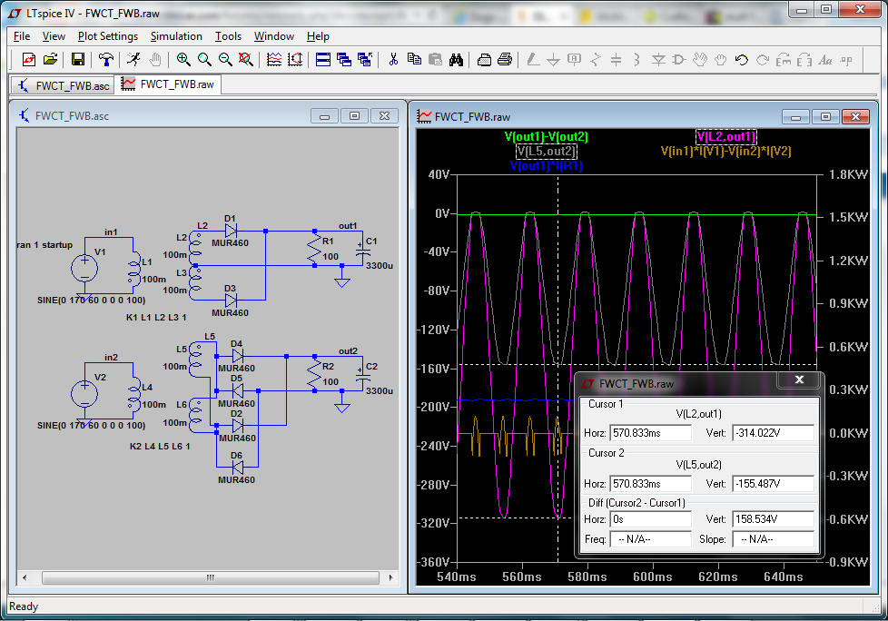
I just tried a simulation of a FWCT and a FWB circuit to see if there is any difference in efficiency or other parameter:

Image


As you can see, the output voltages are essentially identical (the FWCT is about 600 mV higher), and there is some difference in the input power (the FWCT has 611 mW more, probably because of the higher output voltage), but out of 232 watts it is inconsequential. D1 and D3 dissipate 791 mW, while the diodes in the FWB dissipate about 850 mW each. So the FWCT seems to be more efficient.

However, for the same output voltage, the two diodes of the FWCT see about twice the voltage that those in the FWB see. So one must weigh the cost of two diodes in the FWCT of twice the voltage rating of four in the FWB. Also the transformer will need the center tap connection for the FWCT, but as I have shown it, both secondaries are present and they can be connected in series with CT or parallel.
 
#18 ·
Thanks Paul. That's what I thought.

For me, the lower the component count, the better it is. There is no way we would be able to have success with our kits if they had the typical component load found in commercial supplies... Sometimes that does mean some compromises.

Steve - any thoughts on that transformer. We are going to be rewinding our prototype unit tomorrow / Fri. I want to make sure that we take your input into it.

Thanks,
V
 
#19 · (Edited)
I had forgotten that this design is an asymmetric half-bridge converter, with zero voltage switching. I took another look at the application note and now I understand a bit more what is proposed. The blocking capacitor makes this possible. The example is for a 192 watt converter running at 100 kHz, so for your 12 kW converter running at 20 kHz it will need to be roughly 300 times larger than the 220nF, or 69 uF. and it would need to carry continuous current approximately 12000/400 = 30A. Looking for a stock capacitor that would be suitable, I found:
http://www.mouser.com/ProductDetail/Kemet/C4DEHPQ6100A8TK/?qs=sGAEpiMZZMv1cc3ydrPrF6J%2fmgefPq%252bt78QdTHewScs%3d

It is about $60 and, here is the data sheet:
http://www.mouser.com/ds/2/212/F3303_C4DE-123885.pdf

It is rated for 100 amps and an ESR of 800uOhm so its resistive losses would be about 0.72W at 30 amps. This seems like a good idea and would work well even if ZVS were not used. If I understand the concept, the capacitors shown from drain to source of the MOSFETs represent their intrinsic capacitance, and the idea of ZVS is to allow the voltage to discharge as the body diode begins conducting so that the charge will not be dissipated by the forward conduction of the MOSFET.

Another advantage to this design is tolerance for imbalance of the driving waveform. With direct coupling of a full bridge, there could be a net DC voltage and saturation of the transformer. If one of the switching elements opens or shorts, it may result in the destruction of the transformer, whereas for the capacitively coupled design only the MOSFETs or IGBTs might be damaged or destroyed.

A less expensive alternative would be two of these 50 uF 500V capacitors at about $12 each, which are rated 16A and ESR of 4.4 mOhm, which would have losses of about 1 watt each:
http://www.mouser.com/ProductDetail...tail/Panasonic/EZP-E50506MTA/?qs=sGAEpiMZZMv1cc3ydrPrF7yRxWMKYHonRMG0LdR%2bEXg=
http://www.mouser.com/catalog/specsheets/EZP-E.pdf

The compromise of FWCT vs FWB is not as significant since it only involves rectifiers and not IGBTs, so their cost should be fairly low.
 
#20 ·
Yes we are using a large film cap in series with transformer. I think we are going to just build this as a 1:1.2 isolation module that can be inserted between our pfc stage and the buck stage. We will have it run at a fixed 45% duty with a few microsecond deadtime. 1.2 to give us max efficiency on the pfc side. I feel like we can get 93% isolation stage efficiency at 12kw. Combined with 97% on the pfc stage and 98% efficiency on the buck stage at 400v output, we would get a combined efficiency of 88% for the whole thing.
 
#23 ·
309V, 20.8A in
344V, 18.1A out (6.2kW)

efficiency: 96.9%

at least according to the instruments we have available.

this is with new transformer and a system running at fixed 50% duty cycle (symmetric) with ~2uS deadtime, 14kHz switching.

With fans and regular charger heatsink, semiconductor temp rise is <5C. Transformer temp at 10 minutes: 55C. Ambient: 25C

Something tells me that beyond 12kW we will need better cooling for the transformer...

V
 
#26 ·
according to our calculations, at this power level (6.2kW), it's 50:50 and total transformer loss should be at ~30W

at 12kW, it will be 1:4 loss (wire loss is 4x the core). This is by design - as the wire is much easier to cool in forced air.

We use 12 strands of AWG 16 on the primary. AWG 16 is optimal gauge for 20-25khz as it provides good balance between DC and AC resistance from skin effect. 4 strands of same on the secondary. Again, the wire loss is concentrated on the outside of the transformer (in the secondary) by design.

At 12kW, we calculate Core loss at ~15W, Primary copper loss at ~15W, Secondary copper loss at ~35W - for the total of 65W. In still / slow-moving air, that would result in ~70C temp rise on the transformer. About half that with some aggressive forced air cooling.

Based on the loss limits alone, we expect to be able to use this transformer up to 20kW. Our output diodes will have to be upgraded before we can do that. We plan to use 2x of Cree's SiC 1200V 30A diodes in each leg. Hence $120 in just secondary diodes - but their switching is so beautiful ;-)

Wish we could use SiC MOSFETS, too - but a 165A half-bridge from Cree is over $400 on DigiKey so maybe next time ;-)
 
#25 ·
Dividing the current to a larger number of cores makes sense because the core price (and total power) is approx ~ to the weight, but you increase the cooling surface area and decrease the thickness of the material (for the heat coming inside of the core to get out) by using more cores.
 
#27 ·
you are right, of course. But the pain to wind these things is doubled ;)

Also, total space taken is likely to be higher.

Once we have this unit working at satisfactory power level, I want to try integrated magnetics setup, when output inductor is integrated onto the same core as the main transformer. That's still in the advanced domain for me but just a month ago, the whole isolation stage was there, too....
 
#28 · (Edited)
[EDITED to provide corrections for transformer losses]

------------------------------
In: 300V, 52.3A
Out: 308V, 48.0A

Power out: 14.8kW
Eff: 94.2%

Exec Summary: I think we can take this design up to 20kW with some relatively well understood adjustments and some additional thinking on the transformer design per below.


Details:

Transformer temp rise too high to run for more than a few minutes. Need more cooling and reduce losses. Right now the transformer is ~10" away from a small 70CFM fan, with the semi heatsink between the two. Clearly not enough. Also we need to optimize transformer design further (see below).

Overall losses (calculated, ZVS scenario):
1. Transformer: ~300W (80%+ of which are wire losses). Clearly too much.
2. Secondary diodes: ~135W (2.2V drop at 20A * 2 in parallel*0.9 duty)
3. Conduction losses on IGBTs: 190W (1.5V drop at 115A primary current)
4. Switching losses: if no ZVS, would have been 640W.
5. Output inductor: ~40W
6. Input Capacitors: ~160W (0.08R ESR at 14kHz, 8 in parallel, 125A ripple current)
7. Wiring, output capacitors, etc: 20W (? - judging by no perceptible temp rise on any)

TOTAL calculated (if zero switching loss): ~840W
TOTAL measured: ~900W (from 94.2% efficiency)
Close enough.

Analysis:
1. Input elcaps are driven outside of their ripple current rating and dissipate too much. 2 solutions: (a) film caps on input or (b) moving to full-bridge that does not stress input caps. (a) may be expensive as we need ~250uF of film caps at 20kW 20kHz. (b) is expensive and a bit unknown... Film caps solution is 2 legs of 5x 60uF 250VDC caps like http://www.digikey.com/product-detai...223-ND/2783185 - total of ~$100 so not too bad.
2. Transformer would need to be rethought again. EDIT: in previous version of this post we have not accounted for losses due to flux swing from magnetizing current. We got a hint that it might be significant from looking at the scope and seeing a very small curved section on the primary current towards the end of the ON time on one of the IGBT legs when pushed to 16kW. Accounting for flux swing from mag current increases calculated core loss by 10x - from 8W to 75W(!). Needless to say, this is problematic as we can't cool the core very effectively. I think we might have to think about this one a bit more. Parallel transformers might not work as it would be hard to make them absolutely identical for perfect load sharing. Otherwise we could use some standard transformers like http://www.wcmagnetics.com/images/pdf/wcm409.pdf - 2-3 of the larger ones. Perhaps we should try to wind the transformer on a large HighFlux core... Will do some calculations...
3. 50A output current is too much for 32A rated SiC diodes. In production, we would use 2x 43A rated packages per leg. At the above power level, the diode loss would go from 135W to ~80W, or ~50W savings

If these three sources of losses are further optimized (film caps would eliminate input caps loss altogether, optimized transformer would save ~100W, parallel diodes would save 50W), we should be able to get ~250W back, which is ~1.6% of efficiency. That would bring us back to 95-96% territory - which is pretty good for a few weeks of design & testing work.
 
#29 · (Edited)
I have always thought it might be better to use multiple sections of maybe 1-2 kW each. With higher volume of individual components, the cost should come down, and may be better suited to machine assembly of the PCB and the transformers. The surface area of the magnetic components as well as the semiconductors would also increase for better cooling. And there would be redundancy in case of failure, and a means for tailoring the assemblies for various power requirements.

What about using synchronous active rectification? You can get 600V MOSFETs with about 200 mOhms resistance for about $2 each, so a FWCT circuit at 10A each for two devices in series at 50% duty cycle would be about 40 watts for each bridge, and 80 watts for two in parallel at 40 amps. By adding more devices in parallel you might get to 40 watts total with 16 devices or $32. Just a rough estimate, but may have some promise. Some devices that might work:

http://www.mouser.com/ProductDetail...ineon-Technologies/IPB60R190C6/?qs=sGAEpiMZZMshyDBzk1/WixSubO1eivmDRr0KpbEi6Wc=
http://www.mouser.com/ProductDetail...ineon-Technologies/IPP60R125C6/?qs=sGAEpiMZZMshyDBzk1/WixSubO1eivmDtyMd4nZTSw4= ($4, but 125 mOhms and 30A)
http://www.mouser.com/ProductDetail...shay-Siliconix/SIHG47N60EF-GE3/?qs=sGAEpiMZZMshyDBzk1/WiwDTgRIUBA/0tDhwcyURfPg= ($5, but 67 mOhms and 47A)

I have not really worked with synchronous rectifiers, but it seems that you could make a single bridge from four of the last one that would be able to provide 40 amps with about 54 watts dissipation. Perhaps I should run a simulation to see if this is about right.

Also, I found Cree 1200V 2x20A rectifiers for about $40 each:
http://www.mouser.com/ProductDetail...oductDetail/Cree-Inc/C4D40120D/?qs=sGAEpiMZZMtQ8nqTKtFS/Cwtife2N73I17Hl6A1UGQ4=

And there are 1000V 30A ultrafast diodes with about 1.3V at 30A for about $2 each:
http://www.mouser.com/ProductDetail...l/STMicroelectronics/STTH3010W/?qs=sGAEpiMZZMtbRapU8LlZDyPeqYFMplPFuJTEk8CxmYM=
http://www.st.com/st-web-ui/static/active/en/resource/technical/document/datasheet/CD00096486.pdf

and 1200V 40A fast diodes with 1.4V at 40A for $4 each:
http://www.mouser.com/ProductDetail...Semiconductors/VS-40EPF12PBF/?qs=sGAEpiMZZMtbRapU8LlZDwjeQ4GsRwB75LLLqJytF%2bQ=
http://www.mouser.com/ds/2/427/94103-87610.pdf
 
#30 ·
thanks Paul. You may be right, yes. The assembly work does double and cost of components does not scale linearly.

The sync FETs would need to be rated at 1200V for this application which makes regular FETs not applicable and SiC FETs are super-expensive.

The diodes like you mentioned do exist but again, we would need 1200V for secondary tap config. Also, the regular silicon diodes have large reverse recovery charges which results in switching losses and voltage overshoots.

Perhaps if we limit this beast to our standard power rating (12kW), we could take these less ideal avenues. We will try a couple more times with various core materials to see if we can push this to 20kW without undue losses.
 
#31 ·
I liked the wcmagnetics transformers. I sent an inquiry about pricing for a small 5W transformer and also a 2-5 kW model. I like toroids but they do tend to be more expensive, harder to wind, and harder to mount. As a rough estimate of what may be possible in terms of price and performance, I use the 1000 or 1500 watt automotive inverters which are about $50, but of course those are made in ridiculous quantities in China and they are likely to be actually about 500-800W. Still, even $0.10/watt would make a 20 kW switching device about $2000, so it's a reasonable ballpark estimate.

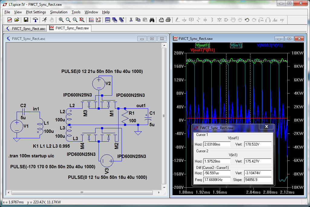
I did a simulation of a synchronous rectifier circuit with FWCT transformer and four MOSFETs on the output. I understand what you are saying about needing better than 600V MOSFETs for a 300-400V output, but perhaps a design with multiple modules in series could produce higher voltages with lower rated devices.

Here's the simulation, FWIW:

Image


I'm not sure how much better the SiC diodes are compared to the ultrafast diodes I found. The SiC Schottky diodes have zero recovery current, but it does have 65-400 uA reverse current which at 600V is as much as 240 mW. Not very significant, but the 2.2-3 volt forward drop at 20A is 44-60W. The Fast 1200V device has just 1.4V at 40A and about 1V at 20A, or 20W, for comparison. The recovery characteristic is 6A for 450 nSec. I'm not sure how to figure the power loss, but if it is 6A at 600V that is 3600W for a duty cycle of about 400 nSec/40 uSec at 25 kHz which is 36W. But that is probably a very high estimate. The ultrafast device has a recovery current of 24A and 50 nSec, so by the same figuring it would be 18W. But the ultrafast versions in the 1200V rating have much higher forward voltage (2V to 4V).

Quite a few trade-offs. ;)
 
#32 ·
Paul, you seem to be very good at building these simulations pretty quickly. Can you simulate a full circuit - with transformers, parasitics, etc? May be worth a go.

Yes, your losses calculation is about right. In a tapped secondary, voltage stress on diodes is at least 2x the output voltage. Hence 900V in this design. In http://www.st.com/st-web-ui/static/active/en/resource/technical/document/datasheet/CD00096486.pdf you mentioned, reverse recovery charge is ~4 micro-C at 30A output current. Times 900V, that means ~3.6 milli-Joules of loss every time it switches. There are 2 diodes switching every cycle, so call it 7 milli-Joules. 20kHz * 7 mJ = 140W total loss. This is at 450V output, this is ~1% of efficiency.

Note that this is not counting any losses from the snubber circuits that you will most likely have to put in to avoid ringing and voltage overshoots from fast reverse recovery.

These things do add up. So generally speaking, SiC devices are much better at these voltage levels. They are expensive, yes, but at least for diodes, once you consider all the adjacencies, using them is actually less expensive (smaller / less complex heatsinks, lower volume, fewer auxiliary parts, etc).

I would say that we got the design into a fairly good place, with the only non-trivial outstanding issue being scaling the transformer beyond ~12kW. After that power level, the losses are just too high.

There are two options I see for solving this:

1. Change core material. I have just done some calculations using datasheets from Magnetics-Inc on their MPP cores. Looks like 2x 133mm OD MPP 125 core may be much better than 2x Ferroxcube 140mm OD we are using. The core loss would be about the same BUT MPP material is spec'ed to 200C, as is the wire insulation. The higher the temp we can run this transformer at, the easier it is to remove the heat. We would also increase the # of strands of wire & make it AWG 20 (instead of 16) to allow us to go to 20kHz without worrying about skin effect.

2. Split the transformer into 2. This is less understood. Anybody has experience at this? Can it be done reliably?

V
 
#33 ·
I received a quote from West Coast Magnetics for some transformers I may need.

2-5 watt $79.50 each (1-9) + $495 NRE engineering

1000 watt $195.50 each (1-9) + $195 NRE engineering (if second item)

5000 watt $429.50 each (1-9) + $125 NRE engineering (if third item)

+ $5 shipping for each order.

I had thought these units were stock or semi-stock which should be cheaper, but there are so many combinations of input and output voltages and power levels that I can understand them being custom. A bit rich for my blood, but perhaps in true production quantities price would drop substantially.

As for simulating the entire circuit with all parameters, that can be difficult, but I can try if you provide the schematic and parts data. I use LTSpice which has models for most of their ICs, and many other parts such as MOSFETs and IGBTs have models available. I had some problems with even this simple circuit because of the high frequency oscillations, but probably some well-placed snubbers and better parameters would eliminate that and allow faster processing. But I can't really simulate a microcontroller.
 
#34 ·
I haven't received mine yet but if your quote is any indication, we won't be interested for sure. It's way cheaper for me to buy cores in volume and have my techs to wind them by hand ;) I am afraid to even think how much they would charge for a toroid transformer ;-0

Re simulation - will do. We would want to simulate only the power circuit but with all parasitics. So ~40-50 components total, with simple square wave input to gates. Will get you the schematics soon.

BTW we have traced our core saturation issue to heating. As ferrite heats up, its ability to hold flux drops. At some point, it resulted in slight saturation that we saw on the scope. So the transformer is fine at 16kW but only until the core heats up to 60-70C. Only if we had a way to cool the core directly... Imagine a liquid cooling loop under the windings, for example. I wonder if anyone seen this done...

Thanks!
V
 
#35 ·
major update on the isolation stage.

With some improved cooling of the transformer from the last pictures posted, we had our first continuous run at 12kW charging one of our converted BMWs (340V CV point, LiFePo4 pack)!

Some stats (steady state):
* Switching at 14kHz
* Efficiency: 94% (isolation stage only)
* Ambient: 22C
* IGBT: <40C
* Secondary rectifier diodes: <40C (note how tiny their common heatsink is! those SiC diodes are amazing!)
* Transformer (outer windings): <60C
* Input caps (elcaps): ~30C
* Blocking cap (large film): ~40C
* Output inductor: <30C

No signs of core saturation. Which proves our hypothesis that previous slight signs of core saturation were caused by the core heatup given inadequate cooling. This time we had a large 40W AC fan blowing directly into the transformer and then into the heatsinks. As you can see, helped quite a bit. After shutting down, temp of transformer surface never exceeded 75C, which probably means that the core did not go above 80-90C.

What does this all mean? It means that our core selection and sizing was not that bad after all. Running a few more strands of somewhat finer wire for the primary and secondary should get us to higher power (as I mentioned before, I think we can get to 20kW with this setup largely unchanged now that we get the transformer run cooler).

This also means that we now have an alternative to $750/kW BRUSA chargers.

This will be released as open source for non-commercial use - same as our non-isolated charger products (http://emotorwerks.com/VMcharger_V12P/ for an idea).

As with our other kits, we will be pricing this around the total cost you would have to pay to procure all the components (including shipping etc). We think it's a pretty good deal. For reference, our 12kW PFC charger kits are ~$1,300 (non-isolated). This is pretty close to the total parts cost + shipping you'd have to pay to 20+ different suppliers ordering in single volume (and some suppliers won't even talk to you for that quantity). That's ~$110/kW. The isolation stage kit, based on our current BOM, would run at less than that. So the complete 12kW isolated charger kit would likely be around $2,500, which is ~$200/kW. Maybe less...

Of course, once we get this stage up to 20kW and connect it to our 25kW controlled PFC stage, economics become even better.

I am pretty excited about this. Are you? ;-)

V

PS. Some quick snaps below. 1) our 12kW PFC charger pumping out ~12kW into the isolation stage. 2) messy prototype of the isolation stage (final production design would be ~ half the size). 3) scope capture - TOP: transformer primary current (100A per major division) showing +/-100A swings at 14kHz. smooth transition between positive and negative is indicative of zero-voltage-switching that saves us ~3% of efficiency (!). also, no signs of core saturation. BOTTOM: gate drive signal for the bottom IGBT.
 

Attachments

#37 ·
another set of great updates at http://www.mynissanleaf.com/viewtopic.php?f=44&t=13349&p=339816#p339816 (also read a couple of preceding pages)

Summary:
1. rewound the transformer a few times on a few different cores
2. got to 20kW peak into a 330V battery (18kW continuous) without any overheating of the transformer
3. expect to get to 25kW at Leaf battery voltage of ~400V
4. still 94% efficiency
5. ready to package up into a standard 10x10x8 box (isolation stage only, full charger requires a regulated PFC stage to feed the isolation stage and control the output - that PFC stage is the same device as our 25kW PFCdirect charger mentioned in http://www.diyelectriccar.com/forums/showthread.php/25-40kw-pfc-charger-high-voltage-82629p5.html
6. getting close to testing full quick-charge protocol on this hardware. Hoping to get to a real demo on a real Nissan Leaf in the next ~4 weeks.

power electronics is fun!

V