DIY Electric Car Forums banner
261 - 280 of 646 Posts
Was a bit too late last night (plus some beers in) and dumb me forgot to add the volatile definition to the variables.
Solved now, the board reads the pilot signal dutycyle and calculates the AC current limit.

If the Proximity indicates a fully seated plug, it then defines the current limit per charger module. Currently the idea is just to share the current over the modules when in single phase connection. Might look at doing a fancy tiered system later.
In a three phase system the module just gets the current limit as is.

Now just to get an EVSE to test the functionality with to see if it will accept the sequencing I have.

Next bit to add to the code is:
  • Plug detection and Pilot signal will have the charger start automatically
  • Canbus controls for limits

In the image you see the serial stream showing, timestamp, AC limit from Pilot, Pilot dutycycle, and then Phase limit for a single phase setup.
 

Attachments

What are the part numbers for the signal connectors?
Id like to make a loom instead of pushing almost fitting pins on the connector.

Damien, do you have an EVSE? Then I could make sure you have some code that will turn the charger on once it detects it is plugged into an EVSE and gets the Pilot signal.

Using Collins code any settings you send it via serial will be saved, thus upon booting it will retain these. Meaning that you could make it a complete standalone charger without the need to talk to it via can.

Unless ofcourse you want to be crazy and run a few of the units in parallel, then can monitoring and control is very handy. ;)
 
Discussion starter · #266 ·
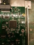
Part numbers for the plugs in the pictures. Have an evse and will test in the Panzer soon with the Ampera battery :)
 

Attachments

Now it should be possible to use the current setting to limit max AC current draw by the charger.

Autostart almost works, however when the Pilot signal gets pulled low by, EVSE_Activate going high the pwm reading freezes. Thus it stops being dynamic and will not respond if the EVSE decides to derate for what ever reason or if the pilot signal stops all together.

Looking now where to scope to see what is happening, most likely an EVSE will not find the signal acceptable.
 
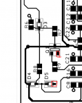
Turns out it were two missing grounds.

Q1 and D5, easily solved with two bits of component leads to a ground through hole.

Code is checked and working, pilot signal gets pulled to +/- 8.7V when plugged in. Then when the proximity is detected it pulls the pilot to 6V (after the fix).

So if anyone wants to try the code to see if the chargers now will kick on and an evse will provide AC power.
Might even be possible to skip the AC relay and just use the commands to the EVSE to trigger the AC power.
 

Attachments

Kevin, i am looking for a car socket.

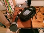
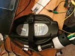
However now using the home adapter I have been able to prove my coding did not work.

Proximity was set to the Type 1 spec (so with push button), however the Type 2 Proximity determines cable amperage.
Now added selectable Type 1 and Type 2 socket, this way you can determine if the power the EVSE will let you draw does not exceed the cable.

Also added a time-out to the Pilot line, so if the period is 20% off it sets the current limit to zero.

I got the green light to turn on and the 240Vac relay to click. :D

Anyone found the temperatures in the can messages?
 

Attachments

Before anyone does extensive testing I would like to get the temperatures figured out so one knows when things are about to melt.

Anyone in need of being able to parallel two of these all of a single phase or split phase? As that would require me to add the functionality of being able to read above 52Amps AC on the pilot.
 
Anyone in need of being able to parallel two of these all of a single phase or split phase? As that would require me to add the functionality of being able to read above 52Amps AC on the pilot.
Several builds are planning to use two chargers and at some point we'll need an option to select between 1 and 3 phase (we'll add a relay to the HVJB to switch the AC fed to the chargers).

Oh, we will also want to support 10+ chargers at some point in the future for our open source SuperCharger ;)
 
In the software there already is one or two phase configuration, I suspect you do not want to change on the fly. As the hardware is complicated because messing up would mean quite a impressive direct short between three phases.

The next step is to do temperature monitoring, which is coming along quite well.

The idea is to have two modes of operation, Master and Slave. The slave just taking commands over CAN.

So for your super charger I would think all will run as slaves.
 
In the software there already is one or two phase configuration, I suspect you do not want to change on the fly. As the hardware is complicated because messing up would mean quite a impressive direct short between three phases.
Not sure what you mean by "on the fly" but Tesla already switch the AC in a small box that staps onto the European HVJB (see slim metal box at bottom of this photo).
 

Attachments

261 - 280 of 646 Posts