DIY Electric Car Forums banner
301 - 320 of 646 Posts
No you need to connect a resistance in series before making a direct connection.

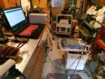
I had time to get a setup built in the shed/garage, I can now say the code works. :D
Latest code on github

Disclaimer, as always this is open source and I take no responsibility for how this information is used. You have a brain yourself, so please use it AC and HV are not to be taken lightly.


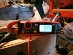
On that note, 10Amps works a treat. Chargers will respond to dynamic current and voltage adjustments.

Next step is to borrow an evse again and wire up my charge socket I just got in. This way I can test the timing to see if switching the EVSE on at the right time removes the need for an AC relay.
 

Attachments

How do you calculate the resistance ohms so you know is not gonna have a surge exceeding it's watt ratings after connecting it?
My understanding is that the Tesla BMS has a relay and a precharge resistor that is closed to bring the voltage and charge the caps on the inverter before closing the main contractors. But I don't understand how they achieve this with a resistance rated to 5kw if it should receive around 7kw from the closing of the relay for the precharge.
Si what is the timing to make it run. I do everything manually except running can via arduino. What I do now.
1. Connect battery
2. Connect 12v then 5V and enable (I see can activity)
3. Feed it with can frames from github to switch it on
4. Connect mains
5. Set voltage via can
6. Set current via can

And nothing happens except extra can traffic.

Sent from my Z1 using Tapatalk
 
using damiens open source board with my latest version of the code:
All info on github for hardware and code : https://github.com/tomdebree/Tesla-Charger


  1. 12V feed to controller and modules
  2. hardware enable to modules to initiate can
  3. Apply HV DC via precharge
  4. Direct connect HV DC
  5. Set Curren and Voltage via Serial to the Controller example : 'v300' 'c10'
  6. activate via serial the charging 's1'
  7. Switch AC mains as soon as the controller shows a setting update

So if you have any other hardware or software your results may vary.
Is there any timeout if mains is feeded too late?


Sent from my Z1 using Tapatalk
 
Discussion starter · #311 ·
Yes the charger modules time out after about 3 seconds if mains is not applied. I would advise you to buy or build one of the control boards as this takes out the messing and now has working software thanks to Tom.
 
Yes the charger modules time out after about 3 seconds if mains is not applied. I would advise you to buy or build one of the control boards as this takes out the messing and now has working software thanks to Tom.
I plan to build one but Tesla charger I have came cheap that I'd like to make sure it works before I invest more.

Sent from my Z1 using Tapatalk
 
Just for pure testing this board is overkill ;-) I use components laying around
afaik no-one has published the CAN messages for the Tesla controller board. If you wish to talk directly to the charger power modules without a controller you can work out the details by reviewing the hardware and software produced by Damien and Tom :)
 
using damiens open source board with my latest version of the code:
All info on github for hardware and code : https://github.com/tomdebree/Tesla-Charger


  1. 12V feed to controller and modules
  2. hardware enable to modules to initiate can
  3. Apply HV DC via precharge
  4. Direct connect HV DC
  5. Set Curren and Voltage via Serial to the Controller example : 'v300' 'c10'
  6. activate via serial the charging 's1'
  7. Switch AC mains as soon as the controller shows a setting update

So if you have any other hardware or software your results may vary.
So you're saying charger will know that battery was connected directly or via precharge?

Any hints on what's good for precharge? Light bulb 100W AC?

Sent from my Z1 using Tapatalk
 
301 - 320 of 646 Posts