DIY Electric Car Forums banner

Tesla BMS

1 reading
62K views 107 replies 23 participants last post by  Tomdb  
#1 · (Edited)
As some of you might have been aware there has been some projects out there that have gotten the Tesla BMS slaves to work.

I have participated in a few. Currently I am working on getting software written to do all the basics like:
-Overvoltage monitoring
-Temperature monitoring
-Undervoltage monitoring
-Balancing during charge
-Current measurement
-AH counter

Outputs
-Contactors/relays or other 12V signals
-PWM 'gas/fuel' gauge control
-Serial interface for Victron VE direct, a special request from Boekel.

The BMS controller/master is based around a teensy 3.2 and code is written in arduino. I will look at uploading my files to github so other can have a look and use it as inspiration.


https://www.youtube.com/watch?v=zmT5o5vDoH8

GITHUB

https://github.com/tomdebree/TeslaBMS
 
#103 ·
If you are using the SimpBMS code, yes pre charge opens again.

The max charge current of the Opensource Tesla Charger is on the AC input side.

You set this to the max your wiring in the car can handle, only in some cases will it be required to be altered for charging using a dumb socket.

When using an EVSE and having the CP and PP wired the Charger will limit its current based on what the EVSE can provide.

Currently there is no DC limiting in the open source chargers, something that has been on my list for while to look at.
 
#102 ·
Hi Tom, I may be getting ahead of myself but I’m controlling the drive/neutral/reverse switching from an arduino with a WiFi board controlled by an android tablet. I will isolate the drive pins to the inverter when I switch the charge pin to high. Will the bms open the precharge contractor once the positive contractor is closed. I am using Damien’s controller for the 72A gen 3 charger, do I set the ‘max charge currrent’ to the max output of the charger ie the DC amperage at pack voltage. Do I need to lower it just in case when using the open EVSE supplying 40A as opposed to the clipper one supplying 80A. If so is there a way to do this once again using a serial adaptor to the pi zero W to enable the changes on the tablet that I’ll be using as a switch control and dashboard.
 
#97 ·
I have 4 Tesla modules, 3 with REV02 BMS slaves and 1 with REV03 BMS slave.
Started installing SIMP-BMS which worked perfectly first.
Now the REV03 BMS slave is showing 5volt more than the module actually is.
I tried swapping slaves but the high voltage discrepancy is in the REV03 slave.

Any ideas would be greatly appreciated. :confused:
 
#95 ·
I'd like to suggest an AUX relay with pre-charge capabilties.
In my conversions the charger, dcdc and PTC heater are on the AUX circuit and need seperate pre-charging before closing the AUX relay (Brusa chargers need pre-charging)


The main relay with pre-charging is just for the motorcontroller.

Also like to have at least 2 PWM controlled outputs for driving the fuel gauge and the inverters output (low output when low SOC)
 
#96 · (Edited)
I'd like to suggest an AUX relay with pre-charge capabilties.
In my conversions the charger, dcdc and PTC heater are on the AUX circuit and need seperate pre-charging before closing the AUX relay (Brusa chargers need pre-charging)
Catered for, precharge is on the positive can change the code so you can use the 'charge' enable relay as an additional negative relay. I will look at including this as an option. This would then work as the following:

Key-On -> in enable both negative contactors and precharge the postive and close it
AC - Present (charger request or what ever you want to call it) -> Aux negative closed and precharge the positive and close it

Also like to have at least 2 PWM controlled outputs for driving the fuel gauge and the inverters output (low output when low SOC)
Read the manual my friend, 4 pwm outputs, all low driving, one does a fuel gauge as standard. The low SOC can be done but the whole thing broadcasts on CAN so you can so you can get really creative with your own Vehicle Controller if you want.

I can ofcourse start looking at making the outputs selectable interms of what they do. However this does increase the risk of someone updating the BMS or connecting for the first time and something going horribly wrong. Or just someone not paying attention and changing a setting they should not change.


Might be worth reading the updated manual
https://www.diyelectriccar.com/forums/showthread.php/fs-tesla-vw-outlander-bms-master-198263.html
 
#94 ·
I have not really updated the hardware schematic. Yes there is a new version of it, but if you want to make one yourself it should be pretty straight forward as all the pins are in the coding.

Also I have them for sale if you want the specific hardware and want to chip in to the development of the next version.

Feel free to leave some feature suggestions.
 
#88 ·
UPDATE 09/11/18

Changed Menu Structure - Update of Manual to follow
New Menu for Charging related variables
- Choosing canbus controlled charger (None, Brusa NLG5xx, Volt Charger)
- Message update speed

Can Bus controlled chargers supported
- AC present high will trigger the charger enable output and start the can comms

---------------------------------------------------------------------------------------

Chargers to be added:
-Eltek
-Open Source Tesla Charger
 
#86 ·


https://www.youtube.com/watch?v=-ItjOXbGdh8

Now also working with the Volt Chargers. This control will also work below the required minimum of 200V by just current limiting the charger till it reaches the desired voltage. This feature however is still at a beta stage and requires further testing.

Reworking the Menu structure slightly need to make some more room
 
#83 ·
Strange serial behaviour I cannot see why, for me its fine.

Link is in the code to the library https://github.com/JonHub/Filters

Only need to re calibrate the offsets with a new sensor or wiring change.

How many slaves are you running?

With the propper working sensor and graph did you have any slaves hooked up?
 
#82 ·
I could not test the new code, it needs filters.h
I do not have that file or know which one it refers to.

I took the bms back to the house, tried it with an other current sensor.
That works great, even the plot works as it should.
I will change sensor in the car and try again.

I do the "c - To calibrate sensor offset" every time i do anything else, rewiring, code change etc.
Tried changing the Range Conv again, when everything else seem to work.
same result

I had this:
Code:
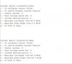
Current Sensor Calibration Menu
c - To calibrate sensor offset
s - To switch between Current Sensors
1 - invert current :1
2 - Pure Voltage based SOC :0
3 - Current Multiplication :1
4 - Analogue Low Range Conv:66.70 mV/A
5 - Analogue High Range Conv:5.70 mV/A
q - Go back to menu
sent 4667

got this:
Code:
Current Sensor Calibration Menu
c - To calibrate sensor offset
s - To switch between Current Sensors
1 - invert current :1
2 - Pure Voltage based SOC :0
3 - Current Multiplication :1
4 - Analogue Low Range Conv:667.00 mV/A
5 - Analogue High Range Conv:5.70 mV/A
q - Go back to menu
 
#81 ·
You should see the value change right away in the menu.
No need.

I have uploaded more code again, please load my code unchanged. This will now also include a 5hz lowpass filter over the current reading.

I would suggest testing just the current sensor and getting reading from it first, with the plot to prove the board is getting the readings it should.
 
#80 ·
Yeah, ok...


I will try as soon as i can.
I have the bms in a box on top of the battery pack, under my car, in a cold garage.
I need to bring it back to the house to test other stuff.


The plot fills up quite slowly, my plot was done in about a minute or so and still not filled up.


I entered "4667".

does it need a space? "4 667"
 
#79 ·
Wierd results. Please check, as because when I enter it i do:

'4 646' and '5 550'

you ran the zero point offsets right, otherwise please show me your current sensor settings menu.

Can you make a setup to run a 'known' wave form (ac current can be done) or a steady current (power supply on current limit).

the plot should fill really quick, does it do that for you?
 

Attachments

#78 · (Edited)
I tried the new code.


I entered 667 at the low range current sensor.
got back 667.00mV/A
tried with 66.7
got back 66.00mV/A
So i edited the .ino file again.
settings.convhigh = 5.7; // mV/A current sensor high range channel
settings.convlow = 66.7; // mV/A current sensor low range channel

now the same menu shows 66.70mV/A

I dont know whats going on with that.

Here is my plot.
I dont know what is going on with that either.
All i know is that as far as my multimeter can tell, the voltage on the sensor is steady as before...
 

Attachments