DIY Electric Car Forums banner
81 - 100 of 138 Posts
Yes, that is what I did on one of my simulations to balance the current draw on each cell. But it may be unnecessary where the current draw of the BMS itself is an order of magnitude greater, but still insignificant for larger packs. If the BMS has shunting resistors, it might be possible for it to identify cells that have a higher charge than others and perform a burst shunt correction to bleed a bit off. This might achieve bottom balancing as the weakest cell shows less charge and triggers charge reduction from the others.

I still think an analog MUX with up to 8 channels would be best. It would need only one divider for all eight cells, and it would only draw current when activated. It will always draw more current from the bottom cell, but with a short duty cycle and a high resistance divider it would be negligible.

Perhaps a differential MUX with two four-channel multiplexers could be used, and a well designed instrumentation amplifier would have two inputs of essentially infinite impedance. There are also eight channel differential MUX devices, or you can use two of the 8-1 devices.

Another possibility is to have a capacitor of some size connected to the outputs of the differential multiplexers. It will essentially draw some energy from the first cell as it charges to the cell voltage. But then as the capacitor is sequentially connected across other cells, it will either draw charge from a "high" cell or inject charge into a "low" cell, thus distributing charge without wasting it in a shunt resistor. This same principle might work during charging as well as discharging. It won't be "perfect", as some power will be dissipated in the resistance of the multiplexer, but it may be a simple way to get a bit more from a poorly balanced pack.
 
for this approach I was looking at a barebones cell monitor with no-balancing, minimal hardware (add cpu & regulator and tx), and I thought it would be kind of cruel if it imposed a constant 300uA imbalance :) (that would be 1% imbalance every 45 days on my 33ah bike)

For a lot of folks it looks like balancing is rarely required, and is a lot simpler than adjusting valves on the sabre (and a cell monitor can help). I'm not looking to get in the OEM market or anything with the barebones approach, but the diy'ers might find it handy and affordable.
 
sorry for space rapping here. Anyway for the "cheap" 8 cell bms, this makes the most sense as far as I can tell, and I wouldn't recommend the network in post 80.

problem is with that one (post 80) is each node is scaled down by the same factor. While it makes sourcing resistors easier, it means the ones lower on the stack have the same bits/volt as the top ones, so the resolution starts out course and stays course. Who cares? Well the thing is the measurements towards the top are essentially differential measurements, based on the reading from the cell below it, and on the cell below that, etc. If we can take advantage of higher resolution lower on the stack, it makes a better foundation to compute the cell values higher up the stack.

So this one is scaled 4:1 on the first node, so that with the 1.1v reference you can measure 4.4v (error!) and the cell voltage is measured in 0.0043v increments. The next one is 8:1 so that when it reads 1.1v at the cpu at 8.8v and the actual cell resolution is in 0.0086v increments, etc: till you get to the top one that is 32:1. If you add up all the errors over 8 readings, it is a bit cringy at 0.158v worst case scenario. (note long settling time needed too). But it is an improvement over the 0.206v accumulated error potential of the one in post 80. But 8 is probably too many for a cheap bms without differential op amps or something. but draw is in the 72uA range and balanced.

At 4 cells (you can just cut this circuit in half removing the higher numbered cells) the accumulated error in the below example is less than 0.05v, which is probably fine for a cheap bms IMHO (assuming you do some calibrating after assembly), and the draw per cell goes down to 36uA. Plus you are into attiny44 (or?) range with 4adc. bla bla bla
 

Attachments

just a note on optos. FYI, again I'm focusing on cheap hardware here, but it has other expenses in time, for sorting it out, and probably calibration/characterization steps. Not saying this is for everyone. But even with "expensive" hardware you still need to validate all your assumptions about it plus research.

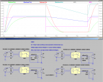
So the main problem with 4 pin optos is the base has no where to drain, so you cant tweak it to get a better (not perfect) output waveform. Here I've kinda split the difference between 2.5v and 4.4v for driving it. Just a rough draft.

If used with a stable vcc then you can dial it in much better both on driving the LED and on getting the right drain rate, but single cpu/cell having stable vcc gets messy.

edit: also you can use it as a photodiode input into an amp by using the base and collector pair and ignoring the emitter which can be very fast, but that might not be a good fit for a single cell driven receiver.
also looked at digital isolators, but those are rather high power (and about $1 apiece) by comparison.

more single cpu thoughts:
was looking at PIC12F1572, better internal voltage reference, but the i/o power is weak for an opto at varying vdd, but lots of threshold/hysterisis options. It can take a crystal, but it doesn't have the same sort of fine grained automatic baud correction as the ATtiny, so extra components (xtal,caps,led driver).
through hole is nice though. And IIRC mplab works w/ubuntu, which is also nice. Maybe an led with a slightly higher voltage than the 4n27 and an npn and a low value resistor to make a "constant current" driver for it, that doubles as, well, an led.


the ATTINY1614 is interesting. i/o is a little stronger, would probably rx without a crystal (clock recovery), which is less power. unknown accuracy on the internal voltage ref, but calibration is needed anyway, at least at room temp (more is better), temp sensor. can use 5 bit characters if comm is weak. Much more familiar with that toolchain too. Plus more pins (mixed blessing, gotta re-eval multiple cells/cpu again).

One side note is with single cpu/board, low power balancing is trivial, just leave the optos/leds on somehow via protocol.

hmm.
 

Attachments

There has been an interesting discussion in Solarsail's thread on the 18650 48V battery pack, for several new ideas for a BMS. I proposed several concepts.

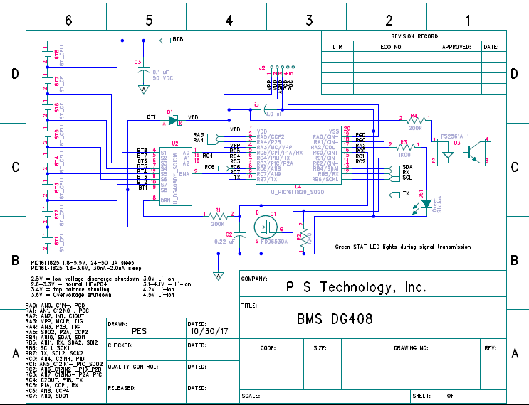
1) The DG408 analog multiplexer could be used on eight cells to connect the voltage taps to a voltage divider to a PIC or other controller. the maximum voltage for LiFePO4 is 3.5 * 8 = 28 VDC, and for Li-Ion is 4.5 * 8 = 36 VDC. The MUX is rated for at least 40V. The processor can be powered from the lowest cell in the stack, which has a voltage range of 2.5 to 3.5 V for LiFePO4 and 3.0 to 4.5 V for Li-Ion. So the internal ADC reference should be set to 2.048 volts. A voltage divider to handle the maximum stack voltage would be 28/2.048 = 13.7/1 for LiFePO4 and 36/2.048 = 17.6/1 for Li-Ion. A 10 bit ADC would provide 28/1024 = 27 mV/count or 35 mV/count. A 12 bit ADC makes these 7 mV/count or 9 mV/count. A voltage divider of 100k would draw at most 36/100 = 360 uA while sampling, and almost nothing when the MUX is disabled.

2) A variation on this circuit uses a resistor and capacitor to charge up to a setpoint of a comparator for each measurement, and the time can determine the voltage. A 250k resistor and 220nF capacitor takes 4.2 mSec for 25.6V (8 cells nominal 3.2V) and 51 mSec for the lowest cell. For a 1 MHz clock, that works out to 4200 counts at 25.6V (6 mV/count), and 51000 counts for 3.2 volts (0.06 mV/count). It is fairly easy to change the clock rate to, say, 100 kHz for the lower voltages, and change the RC integrator to 500k and 470nF for 240 mSec to 2.048V and 3.2V. A 100 kHz clock would read 24,000 counts or 133 uV/count. The capacitor is discharged after each reading. Here is a preliminary design:

Image


3) Using two DG408 multiplexers, it is possible to sample each cell voltage by charging a capacitor. When the MUX is disabled, the capacitor will be floating. Then another MUX could connect the capacitor to the ADC input of the microcontroller. The only problem is that the capacitor could be charged to as much as 4.5 volts, which would also be the power supply for the processor, and the reference would need to be less, perhaps 2.048V. This issue might be solved with a 2.5/1 voltage divider, but that would start discharging the sampling capacitor. A separate op-amp powered from the bottom two cells (6.4V nominal) could provide the drive to the voltage divider without affecting the charge.

This method utilizes the full range of the ADC, so 10 bits on 3.2 volts is 3.1 mV/count, and for 12 bits it is 780 uV/count.

Another feature of this flying capacitor design is that the charge from a higher voltage cell would be transferred to a lower cell. The amount of balancing would be minimal, but the sampling process draws very little current from the pack.

4) More effective shunt balancing can be accomplished by using Darlington opto-isolators, such as PS2502-4, which is a quad device capable of 160 mA per channel, and costs only about $2. A 22 ohm resistor would dissipate the power, which is only about 1/2 watt. If stronger shunt balancing is needed, a MOSFET could be added to each cell.

5) Communication between 8-cell modules can be done using digital isolators like the Si8621A which has two channels, draws less than 2mA, handles up to 1 Mb/sec, and costs about $1.00, using the Txd and Rxd of the USART of the PIC or other device. it draws about 2 mA but could be powered off at a low duty cycle.

6) The Txd and Rxd may also be connected to a Bluetooth module for remote monitoring and control. However, it uses as much as 100 mA so that might be a problem.

7) An LCD display module could be added to the I2C or SPI interface, but also may draw too much current to be practical.
 
couple thoughts if you don't mind.

re: 4 pin opto, see above. Also re: digital isolator, both sides need to wake up and power it, so how do you communicate to the receiving side that it is time to wake up, opto is more flexible there.

still trying to sort out the details of the DG408, will get back to you on that but definitely a possibility, depending on how it affects calibration/characterization. It *looks* like it is applying 36v to the cpu at times, but with the 200k resistor it isn't going to fry anything, but still probably clamping. I think you do need another one (or might just as well use the resistor network) to float both ends of the cap to the cell then bring it back down to adc ground reference for measurement. If you stagger the pins between them by 1 I think you can just give them the same address and the d-outs will be the difference (connected to capacitor), just leave cell 1 out of it on the higher shifted dg408 (and compensate for any reading differences on it) and use that multiplexer pin to feed the adc when you shift it back down and the same pin on the other dg408 to ground the other end of the capacitor. Lemme know If I need to draw a picture. But you are up to $2-$3 for the pair.


how many digits do we really need though, srsly, I mean the more the better, but I'd be happy with 8 bits over 5v equivalent, as long as it is accurate, i.e. 0.02v, folks *should* be using enough charge/discharge safety margin that it won't matter, even 2/10 of a volt imbalance isn't an action item for me as long as it stops charging when the highest cell gets to 4 or 4.1v.

supply voltage, maybe a balance resistor on the top cells to match bottom cell drain, dunno, I'm being nitpicky.

Another issue is I just thought of is, say you are at 3v, and you (lets say leaf cells) decide to briefly tap them for 500 amps, well the voltage will drop below 2 volts. Perfectly "reasonable" scenario. I appreciate 1.8v is a "hard" limit on the cpu, but ideally nothing else is going to increase that limit to a higher value. And dropping below 2.5v is reasonable under load.

Fwiw, I'm trying to imagine a pin controlled dual power zener limiter/divider for an "active" power supply and a sleep supply. Mostly it is the high side resistor that needs to change, perhaps a pnp (or p-channel, but pnp is prolly cheaper) bypass through a lower value resistor for "high power" mode, feeding a carefully chosen zener and capacitor in parallel. Also wary of reading 8 cell voltage if the dg408 v+ is below the rail cuz of the pnp, actually that might be a problem if it were at the rail.
 
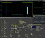
here is the "dual mode" zener regulator rough draft, tweak r12 to suit your minimum power requirements while sleeping. When off it is drawing 29 micro amps, not entirely sure why npn is working with so little base current, so just some fudging around in a simulator.

Draws 25ma from pack when ON, 12 for the opto and 13 in "reserve" being dumped by the zener for the most part, voltage relatively stable. Lots of little and ultimately very carefully selected parts though, is there a chip that will do this that isn't costly? I suppose matching it to the needs of everything else is the hard part.

r10 is just simulating a gpio pin going high when the cpu wakes up.

So this is meant to be part of a system where it will turn off each bms node when not charging or driving, but the bms nodes draw just enough power that they can respond to a "wake up" call. And no more built-in imbalance within the node plus a much more stable voltage to work from (well, it has a bit of ripple, but it stays high regardless of cell voltage). But it is "riding the knee" on the zener here in low power mode, so that might be weird when temperature changes. changing r12 makes the low power vdd 4.2v and draws 560uA from the cells at full charge and 200uA at low charge, so definitely some room to play with there in exchange for overall discharge rate.

I suppose a linear regulator is the next obvious choice if it can handle 36v, though those start at ~2ma quiescent, and no spec for current rating at 36v.
 

Attachments

I don't think such a complicated power supply is needed for the microcontroller. The low cell can supply it through a Schottky diode, so even at a minimum voltage of 2.5 volts the PIC will see about 2.3 volts. A small supercapacitor could be used to hold the voltage in case a sudden current surge drops the cell to less than 2 volts.

There are also charge pump devices that can boost low voltages. They can be as much as 98% efficient.

It may be possible to tweak an extra bit of resolution from the ADC by setting the positive reference to 2.048V and the negative reference to 1.024V. With a 2.3/1 voltage divider this would measure 2.355 to 4.710 volts, with a precision of 2.3 mV/count.
 
is that lower vref thing a microchip specific trick?

yah the zener thing is a little complicated, but guarantees balance and allows the occasional dip, and overcomes the draw problems with just a zener, any voltage regulator is gonna look funky on the inside, this is just an attempt at special purpose one (we are looking at just the power supply section, right?) without getting too fancy.

re supercaps and charge pumps, probably would rather just see a buck converter on the whole stack (could be charge pump too), driving an opto is 10's of milliamps, really any decent signal needs a bit of power behind it, and standard uart is active high by default (and emitter follower seems to be the best response mode for an opto).

But 5v capable supercaps start at $1.73! more of a marketing gimmic IMHO, not really sure why trying to make 1 cell in charge of the whole stack.


fwiw, instead of single cpu/board I'm leaning towards a two cell module these days and a suitable ldo regulator. Still reasonable resolution on both cells (~0.01v), enough voltage headroom to handle the occasional tromp, while minimizing differences in vdd (and associated headaches) half the interconnects and optos, still a real simple sensing circuit, just 2 dividers and a balance resistor for the upper cell, the ldo (and prolly a cap or two), an opto and resistors, led, and a cpu. And I don't think having multiples of 2 cells is an oppressive design requirement for a vehicle (actually kind of hard to avoid if using leaf cells). Just trying to find the "right" ldo currently. Hopefully small enough pcb that you can bond it to the cell and get some temperature hints, mebbe I should avoid through hole for that reason alone, but also want to avoid having folks soldering on grains of rice...

also for quick and easy pcb design I'm looking at this. http://fritzing.org/ so as not to scare too many people off w/the process. But also looking into other alternatives as it is a bit arduino centric.
 
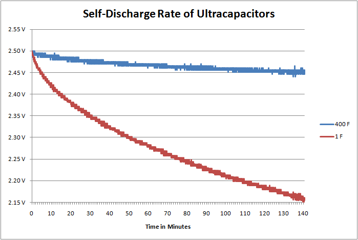
Where did you get that curve? What I found indicates adequate voltage for as long as seven days. The voltage only needs to hold during such times as the pack is being discharged at a very high current, as during acceleration, which is just a few seconds.

https://www.tecategroup.com/ultraca...capacitors/ultracapacitor-FAQ.php#What_is_the_self_discharge_or_leakage_current

Image


Regarding ADC positive and negative references, I think most PICs have both, and the Atmel devices probably do as well. The Atmel ATMega series have only a positive reference. What I found:

http://www.atmel.com/Images/Atmel-8...t-AVR-Microcontrollers-AVR127-Understanding-ADC-Parameters_Application-Note.pdf

http://www.atmel.com/Images/doc8060.pdf

http://extremeelectronics.co.in/microchip-pic-tutorials/using-adc-of-pic-microcontroller/

I am not sure if the Vref- can be set to 1/2 Vref+, however.
 
so no part numbers on those graphs, the one I posed was kinda old too.

The thing to note is rp in this picture from your same link:
Image


From my understanding you want to feed the cap from the bottom cell through a diode, well you will be feeding rp from the bottom cell as well, creating a measure of imbalance.

so lets look at a $1.70 5.5v 10mF cap (you don't want to put a couple 2.7 in series and have to worry about their balance as well, also mentioned in your link)

https://content.kemet.com/datasheets/KEM_S6015_FY.pdf

this was the first one that gave any hints about self discharge in the 5-6v range, and instead of being precise (well the capacitance itself is −20/+80%!) about rp, they gave this information:
discharge from 5v to 4.2v in 24 hours no load. So it would be like putting a 50meg resistor in parallel with the lowest cell, not really a deal killer in the cell balance part which was my main concern (~0.8uA at full charge). It might be suitable for a single cpu per cell arrangement though if that was your meaning, but not at $1.73 apiece :)

but you are still running a microcontroller and opto and multiplexer and led and a mosfet and various bias resistors and whatnot from that one cell though, to monitor 8 cells. That is definitely a concern in the balance department, especially if it were on a string of small capacity cells.
 
Perhaps an efficient buck converter powered by the eight cells to provide power for the controller would be a way to assure equal drain on all cells. A linear regulator would cause roughly 8 times the drain on the pack and that would not be very efficient. The charge shuttling option would tend to reverse the effects of the drain on the bottom cell. If it is lower in voltage than the others, it would be charged from the higher voltages of those in the upper cells.

It is possible to apply the selected cell voltages to the power supply of the PIC, and use that as the Vref+ of the ADC. The input to the ADC would be the internal reference voltage, 2.048 VDC. The PIC Vdd can be determined in this way.

A 100,000 uF 5.5V ultracapacitor is only $1.45 in quantities of 10:
https://www.mouser.com/ProductDetai...l/KEMET-NEC-Tokin/FYD0H104ZF/?qs=sGAEpiMZZMuDCPMZUZ%2bYl5h6rep0zAk/0j/ffoOkOEQ=

Here are 4 farad 5.5 volt capacitors $10.39 for 10 pieces:
https://www.banggood.com/10pcs-5_5V...tor-Double-Layer-Capacitor-Low-ESR-p-1213342.html?rmmds=search&cur_warehouse=CN
 
well I'm considering 2 cells per node to give the extra voltage headroom and not lose too much accuracy on the top cell, so the losses from a ldo won't be so bad there, vs 8 cells. 8 cells has challenges in that department, but if the buck converter costs less than 4 ldo then you will be ahead in the cost/cell in that department (8 cell is already ahead in the cpu/cell dept cost, and prolly pcb/cell cost). But you will need another multiplexer if you are trying for accuracy on the upper cells.

The multiplexer is interesting, but does it behave differently near the rail? I know with a simple differential op-amp it is less concern since you are dividing the inputs, but not sure here, but you need more adc pins for that (but no address line concerns).

With the required current limiting I don't see it being practical for charge shuttling though.
 
It looks like I (or someone) needs to build a prototype to test various designs. I also have some other ideas:

1) I found an MOSfet opto-isolator TLP175A for about 60 cents in 100 piece quantity, with an LED trigger current of 1 mA maximum. So there could be eight of these connected to each tap of the battery pack, to sample each cell into a flying capacitor. Then two more would connect the capacitor to the ADC input of the controller. This does add $5.40 to the cost, but replaces the cost of two DG408 multiplexers, $2.80 in quantity 10. It is also extensible to any number of cells, as long as the controller has enough I/O pins to turn on pairs of the optos. Two 74HC138 3-8 encoders ($0.28 each) can do the selection with 3 I/O pins each, and one more I/O for the measurement. For 16 cells, 74HC154 ($0.68 each) can be used. This system also can be used for lead-acid 12V battery packs up to 96 volts or 192 volts.

2) Using the DG408 multiplexers, a differential or instrumentation amplifier can be used to read voltages on the battery pack taps at ground level of the processor. The AD8420 is only $2.45 in quantity 10 and can operate at 36 VDC with current draw of 90 uA.
 
re: tlp175a, has 5ms turn on/turn off delay though, probably has the same issues as other 4 pin optos (gate has no where to drain) but I don't know why the turn on time is so slow, the $0.20 4n27 has similiar power levels and about 5us turn on and off with an appropriate base drain. See post 48. You are looking at best 100 baud with that mosfet unless I'm doing it wrong. Maybe there are mitigating factors you have in mind that make 100 baud ok? I'm thinking of token ring so it would kill what I have in mind.

I'm working on an tiny1614 board, but still experimenting with different layout tools, really tired of the crap I've been using.
 
The TLP175A is to be used for sampling the cell voltage to a flying capacitor, so the 5 mSec maximum (1 mSec typical) response time is adequate. Faster and cheaper devices can be used for communication.

It can also handle 100 mA with a 50 ohm resistance (500mW) so they might be able to perform some cell balancing by connecting to a floating load. Actually two in series are 100 ohms and with 3.6 volts on a cell that is just 36 mA.

The TLP222A can handle 500 mA with a 2 ohm ON resistance, and is not terribly expensive at $0.97 each in 100 piece quantity.

I use Mentor Graphics PADS2004sp2 for schematics and layout with pretty good autorouting. But it's rather costly. I tried KiCad years ago and didn't much like it, but I have heard it is now much improved, and it is open source.

I have DesignSpark and ExpressPCB, mostly to open the files others have supplied. DipTrace is another I have heard of. No real experience with any of them, though.
 
It looks like I (or someone) needs to build a prototype to test various designs. I also have some other ideas:

1) I found an MOSfet opto-isolator TLP175A for about 60 cents in 100 piece quantity
You thinking like this? http://www.falstad.com/circuit/circuitjs.html?cct=$+1+0.000005+10.20027730826997+50+5+43%0Av+208+64+208+16+0+0+40+5+0+0+0.5%0Aw+208+16+208+0+0%0Aw+272+0+320+0+0%0Aw+320+0+320+16+0%0Aw+320+64+320+80+0%0Aw+272+64+320+64+0%0Aw+320+128+320+144+0%0Aw+272+128+320+128+0%0Aw+320+192+320+208+0%0Aw+272+192+320+192+0%0Aw+320+256+320+272+0%0Aw+272+256+320+256+0%0Aw+320+320+320+336+0%0Aw+272+320+320+320+0%0Av+208+128+208+64+0+0+40+5+0+0+0.5%0Av+208+384+208+320+0+0+40+5+0+0+0.5%0Av+208+320+208+256+0+0+40+5+0+0+0.5%0Av+208+256+208+192+0+0+40+5+0+0+0.5%0Av+208+448+208+384+0+0+40+5+0+0+0.5%0Av+208+192+208+128+0+0+40+5+0+0+0.5%0Ag+208+448+208+464+0%0Aw+384+368+384+304+0%0Aw+384+304+384+240+0%0Aw+384+240+384+176+0%0Aw+384+176+384+112+0%0Aw+384+112+384+48+0%0Aw+320+368+384+368+0%0Aw+384+304+320+304+0%0Aw+320+240+384+240+0%0Aw+384+176+320+176+0%0Aw+320+112+384+112+0%0Aw+384+48+320+48+0%0Aw+208+320+272+320+0%0Aw+272+256+208+256+0%0Aw+208+192+272+192+0%0Aw+272+128+208+128+0%0Aw+208+64+272+64+0%0Aw+272+0+208+0+0%0Aw+208+64+144+64+0%0Af+144+32+96+32+8+1.5+0.02%0Aw+96+48+96+64+0%0Aw+96+64+144+64+0%0Aw+48+400+48+336+0%0Aw+48+336+48+272+0%0Aw+48+272+48+208+0%0Aw+48+208+48+144+0%0Aw+48+144+48+80+0%0Aw+48+80+48+16+0%0A209+0+-16+0+32+0+0.000001+4.969841241799555+1%0Aw+48+-16+384+-16+2%0Aw+384+-16+384+48+0%0Aw+208+384+272+384+0%0Aw+320+432+384+432+0%0Aw+272+384+320+384+0%0Aw+320+384+320+400+0%0Aw+384+432+384+368+0%0Af+272+32+320+32+1+1.5+0.02%0Af+272+96+320+96+1+1.5+0.02%0Af+272+160+320+160+1+1.5+0.02%0Af+272+224+320+224+1+1.5+0.02%0Af+272+288+320+288+1+1.5+0.02%0Af+272+352+320+352+1+1.5+0.02%0Af+272+416+320+416+1+1.5+0.02%0Ar+272+96+240+96+0+1000%0Ar+272+160+240+160+0+1000%0Ar+272+224+240+224+0+1000%0Ar+272+288+240+288+0+1000%0Ar+272+352+240+352+0+1000%0Ar+272+416+240+416+0+1000%0Ar+272+32+240+32+0+1000%0AR+240+32+240+16+0+0+40+50+0+0+0.5%0Aw+240+160+240+96+0%0Aw+240+96+240+32+0%0Aw+240+224+240+288+0%0Aw+240+288+240+352+0%0Aw+240+352+240+416+0%0Ar+144+32+176+32+0+1000%0Aw+96+16+48+16+0%0Aw+96+80+48+80+0%0Aw+96+128+144+128+0%0Aw+96+112+96+128+0%0Af+144+96+96+96+0+1.5+0.02%0Aw+208+128+144+128+0%0Aw+96+144+48+144+0%0Aw+96+192+144+192+0%0Aw+96+176+96+192+0%0Af+144+160+96+160+0+1.5+0.02%0Aw+208+192+144+192+0%0Aw+96+208+48+208+0%0Aw+96+256+144+256+0%0Aw+96+240+96+256+0%0Af+144+224+96+224+0+1.5+0.02%0Aw+208+256+144+256+0%0Aw+96+272+48+272+0%0Aw+96+320+144+320+0%0Aw+96+304+96+320+0%0Af+144+288+96+288+0+1.5+0.02%0Aw+208+320+144+320+0%0Aw+96+336+48+336+0%0Aw+96+384+144+384+0%0Aw+96+368+96+384+0%0Af+144+352+96+352+0+1.5+0.02%0Aw+208+384+144+384+0%0Aw+96+400+48+400+0%0Ar+144+416+144+448+0+1000%0Aw+96+448+144+448+0%0Aw+96+432+96+448+0%0Af+144+416+96+416+0+1.5+0.02%0Aw+208+448+144+448+0%0Aw+144+0+208+0+0%0Aw+48+-16+0+-16+0%0Aw+48+16+0+32+2%0Aw+240+224+240+160+0%0Ag+176+32+176+48+0%0Ag+176+96+176+112+0%0Ar+144+96+176+96+0+1000%0Ag+176+160+176+176+0%0Ar+144+160+176+160+0+1000%0Ag+176+224+176+240+0%0Ar+144+224+176+224+0+1000%0Ag+176+288+176+304+0%0Ar+144+288+176+288+0+1000%0Ag+176+352+176+368+0%0Ar+144+352+176+352+0+1000%0Aw+272+448+208+448+0%0A159+272+448+272+416+0+20+10000000000%0A159+272+384+272+352+0+20+10000000000%0A159+272+320+272+288+0+20+10000000000%0A159+272+256+272+224+0+20+10000000000%0A159+272+192+272+160+0+20+10000000000%0A159+272+128+272+96+0+20+10000000000%0A159+272+64+272+32+0+20+10000000000%0A159+144+0+144+32+0+20+10000000000%0A159+144+64+144+96+0+20+10000000000%0A159+144+128+144+160+0+20+10000000000%0A159+144+192+144+224+0+20+10000000000%0A159+144+256+144+288+0+20+10000000000%0A159+144+320+144+352+0+20+10000000000%0A159+144+384+144+416+0+20+10000000000%0Aw+288+432+608+224+0%0Aw+128+400+608+272+0%0Aw+288+368+608+192+0%0Aw+128+336+608+192+0%0Aw+128+272+608+160+0%0Aw+288+304+608+160+0%0Aw+128+208+608+128+0%0Aw+288+240+608+128+0%0AL+608+224+640+224+0+0+false+5+0%0AL+608+192+640+192+0+0+false+5+0%0AL+608+160+640+160+0+0+false+5+0%0AL+608+128+640+128+0+0+false+5+0%0Aw+128+144+608+96+0%0Aw+288+176+608+96+0%0Aw+128+80+608+64+0%0Aw+288+112+608+64+0%0Aw+128+16+608+32+0%0Aw+288+48+608+32+0%0AL+608+96+640+96+0+0+false+5+0%0AL+608+64+640+64+0+0+false+5+0%0AL+608+32+640+32+0+0+false+5+0%0Ad+608+224+608+272+1+0.805904783%0Ad+608+304+608+272+1+0.805904783%0AL+608+304+640+304+0+0+false+5+0%0Ap+-112+224+-112+400+1+0%0Aw+-112+400+96+448+0%0Af+-64+208+-112+208+0+1.5+0.02%0Ar+-64+208+-64+240+0+10000%0Ag+-64+240+-64+256+0%0Aw+-112+192+-112+-16+0%0Aw+-112+-16+0+-16+0%0Aw+-112+400+-144+400+0%0Aw+-112+224+-144+224+0%0Ar+-144+224+-144+400+0+1000000%0A159+-64+208+-64+144+0+20+10000000000%0Aw+-48+176+16+464+0%0Aw+16+464+512+480+0%0Aw+512+480+608+304+0%0Aw+-64+144+96+64+0%0Ao+48+64+0+4099+10+0.1+0+2+48+3%0A

I wonder what size cap and switching freq would be needed to have an effect on balancing. maths for another day I think

I have a bunch of PS2501-4's only 50ma tho. but should be plenty to test on some hobby lipo's
 
You thinking like this? http://www.falstad.com/circuit/circuitjs.html?cct=$+1+0.000005+10.20027730826997+50+5+43%0Av+208+64+208+16+0+0+40+5+0+0+0.5%0Aw+208+16+208+0+0%0Aw+272+0+320+0+0%0Aw+320+0+320+16+0%0Aw+320+64+320+80+0%0Aw+272+64+320+64+0%0Aw+320+128+320+144+0%0Aw+272+128+320+128+0%0Aw+320+192+320+208+0%0Aw+272+192+320+192+0%0Aw+320+256+320+272+0%0Aw+272+256+320+256+0%0Aw+320+320+320+336+0%0Aw+272+320+320+320+0%0Av+208+128+208+64+0+0+40+5+0+0+0.5%0Av+208+384+208+320+0+0+40+5+0+0+0.5%0Av+208+320+208+256+0+0+40+5+0+0+0.5%0Av+208+256+208+192+0+0+40+5+0+0+0.5%0Av+208+448+208+384+0+0+40+5+0+0+0.5%0Av+208+192+208+128+0+0+40+5+0+0+0.5%0Ag+208+448+208+464+0%0Aw+384+368+384+304+0%0Aw+384+304+384+240+0%0Aw+384+240+384+176+0%0Aw+384+176+384+112+0%0Aw+384+112+384+48+0%0Aw+320+368+384+368+0%0Aw+384+304+320+304+0%0Aw+320+240+384+240+0%0Aw+384+176+320+176+0%0Aw+320+112+384+112+0%0Aw+384+48+320+48+0%0Aw+208+320+272+320+0%0Aw+272+256+208+256+0%0Aw+208+192+272+192+0%0Aw+272+128+208+128+0%0Aw+208+64+272+64+0%0Aw+272+0+208+0+0%0Aw+208+64+144+64+0%0Af+144+32+96+32+8+1.5+0.02%0Aw+96+48+96+64+0%0Aw+96+64+144+64+0%0Aw+48+400+48+336+0%0Aw+48+336+48+272+0%0Aw+48+272+48+208+0%0Aw+48+208+48+144+0%0Aw+48+144+48+80+0%0Aw+48+80+48+16+0%0A209+0+-16+0+32+0+0.000001+4.969841241799555+1%0Aw+48+-16+384+-16+2%0Aw+384+-16+384+48+0%0Aw+208+384+272+384+0%0Aw+320+432+384+432+0%0Aw+272+384+320+384+0%0Aw+320+384+320+400+0%0Aw+384+432+384+368+0%0Af+272+32+320+32+1+1.5+0.02%0Af+272+96+320+96+1+1.5+0.02%0Af+272+160+320+160+1+1.5+0.02%0Af+272+224+320+224+1+1.5+0.02%0Af+272+288+320+288+1+1.5+0.02%0Af+272+352+320+352+1+1.5+0.02%0Af+272+416+320+416+1+1.5+0.02%0Ar+272+96+240+96+0+1000%0Ar+272+160+240+160+0+1000%0Ar+272+224+240+224+0+1000%0Ar+272+288+240+288+0+1000%0Ar+272+352+240+352+0+1000%0Ar+272+416+240+416+0+1000%0Ar+272+32+240+32+0+1000%0AR+240+32+240+16+0+0+40+50+0+0+0.5%0Aw+240+160+240+96+0%0Aw+240+96+240+32+0%0Aw+240+224+240+288+0%0Aw+240+288+240+352+0%0Aw+240+352+240+416+0%0Ar+144+32+176+32+0+1000%0Aw+96+16+48+16+0%0Aw+96+80+48+80+0%0Aw+96+128+144+128+0%0Aw+96+112+96+128+0%0Af+144+96+96+96+0+1.5+0.02%0Aw+208+128+144+128+0%0Aw+96+144+48+144+0%0Aw+96+192+144+192+0%0Aw+96+176+96+192+0%0Af+144+160+96+160+0+1.5+0.02%0Aw+208+192+144+192+0%0Aw+96+208+48+208+0%0Aw+96+256+144+256+0%0Aw+96+240+96+256+0%0Af+144+224+96+224+0+1.5+0.02%0Aw+208+256+144+256+0%0Aw+96+272+48+272+0%0Aw+96+320+144+320+0%0Aw+96+304+96+320+0%0Af+144+288+96+288+0+1.5+0.02%0Aw+208+320+144+320+0%0Aw+96+336+48+336+0%0Aw+96+384+144+384+0%0Aw+96+368+96+384+0%0Af+144+352+96+352+0+1.5+0.02%0Aw+208+384+144+384+0%0Aw+96+400+48+400+0%0Ar+144+416+144+448+0+1000%0Aw+96+448+144+448+0%0Aw+96+432+96+448+0%0Af+144+416+96+416+0+1.5+0.02%0Aw+208+448+144+448+0%0Aw+144+0+208+0+0%0Aw+48+-16+0+-16+0%0Aw+48+16+0+32+2%0Aw+240+224+240+160+0%0Ag+176+32+176+48+0%0Ag+176+96+176+112+0%0Ar+144+96+176+96+0+1000%0Ag+176+160+176+176+0%0Ar+144+160+176+160+0+1000%0Ag+176+224+176+240+0%0Ar+144+224+176+224+0+1000%0Ag+176+288+176+304+0%0Ar+144+288+176+288+0+1000%0Ag+176+352+176+368+0%0Ar+144+352+176+352+0+1000%0Aw+272+448+208+448+0%0A159+272+448+272+416+0+20+10000000000%0A159+272+384+272+352+0+20+10000000000%0A159+272+320+272+288+0+20+10000000000%0A159+272+256+272+224+0+20+10000000000%0A159+272+192+272+160+0+20+10000000000%0A159+272+128+272+96+0+20+10000000000%0A159+272+64+272+32+0+20+10000000000%0A159+144+0+144+32+0+20+10000000000%0A159+144+64+144+96+0+20+10000000000%0A159+144+128+144+160+0+20+10000000000%0A159+144+192+144+224+0+20+10000000000%0A159+144+256+144+288+0+20+10000000000%0A159+144+320+144+352+0+20+10000000000%0A159+144+384+144+416+0+20+10000000000%0Aw+288+432+608+224+0%0Aw+128+400+608+272+0%0Aw+288+368+608+192+0%0Aw+128+336+608+192+0%0Aw+128+272+608+160+0%0Aw+288+304+608+160+0%0Aw+128+208+608+128+0%0Aw+288+240+608+128+0%0AL+608+224+640+224+0+0+false+5+0%0AL+608+192+640+192+0+0+false+5+0%0AL+608+160+640+160+0+0+false+5+0%0AL+608+128+640+128+0+0+false+5+0%0Aw+128+144+608+96+0%0Aw+288+176+608+96+0%0Aw+128+80+608+64+0%0Aw+288+112+608+64+0%0Aw+128+16+608+32+0%0Aw+288+48+608+32+0%0AL+608+96+640+96+0+0+false+5+0%0AL+608+64+640+64+0+0+false+5+0%0AL+608+32+640+32+0+0+false+5+0%0Ad+608+224+608+272+1+0.805904783%0Ad+608+304+608+272+1+0.805904783%0AL+608+304+640+304+0+0+false+5+0%0Ap+-112+224+-112+400+1+0%0Aw+-112+400+96+448+0%0Af+-64+208+-112+208+0+1.5+0.02%0Ar+-64+208+-64+240+0+10000%0Ag+-64+240+-64+256+0%0Aw+-112+192+-112+-16+0%0Aw+-112+-16+0+-16+0%0Aw+-112+400+-144+400+0%0Aw+-112+224+-144+224+0%0Ar+-144+224+-144+400+0+1000000%0A159+-64+208+-64+144+0+20+10000000000%0Aw+-48+176+16+464+0%0Aw+16+464+512+480+0%0Aw+512+480+608+304+0%0Aw+-64+144+96+64+0%0Ao+48+64+0+4099+10+0.1+0+2+48+3%0A
You broke the vscope track every movement bot with that link :)
 
81 - 100 of 138 Posts